
In the winter of 2013, LED strip lighting hit its tipping point – a big rise in popularity.
A year beforehand, in 2012, I had an idea to build a controller for LED strip lighting. A sound reactive LED controller – to make the lights get brighter on the bass notes. Biggest problem – I didn’t know how to make one.
I finally started getting comfortable with electronics in 2014.
But in 2014, Asian controllers were appearing on eBay. All relied on microphones for audio input and didn’t work well, often they were useless. The Apollo Jammer was the best (no longer for sale now). It was a fully digital design capable of driving RGB LEDs for $100.
If I could make a Sound Reactor for $30, I could tap into the market of cheap college students, teenagers, and millennials. Thinking the digital design was what made this expensive, I pursued an analog approach. The following is a post-mortem.
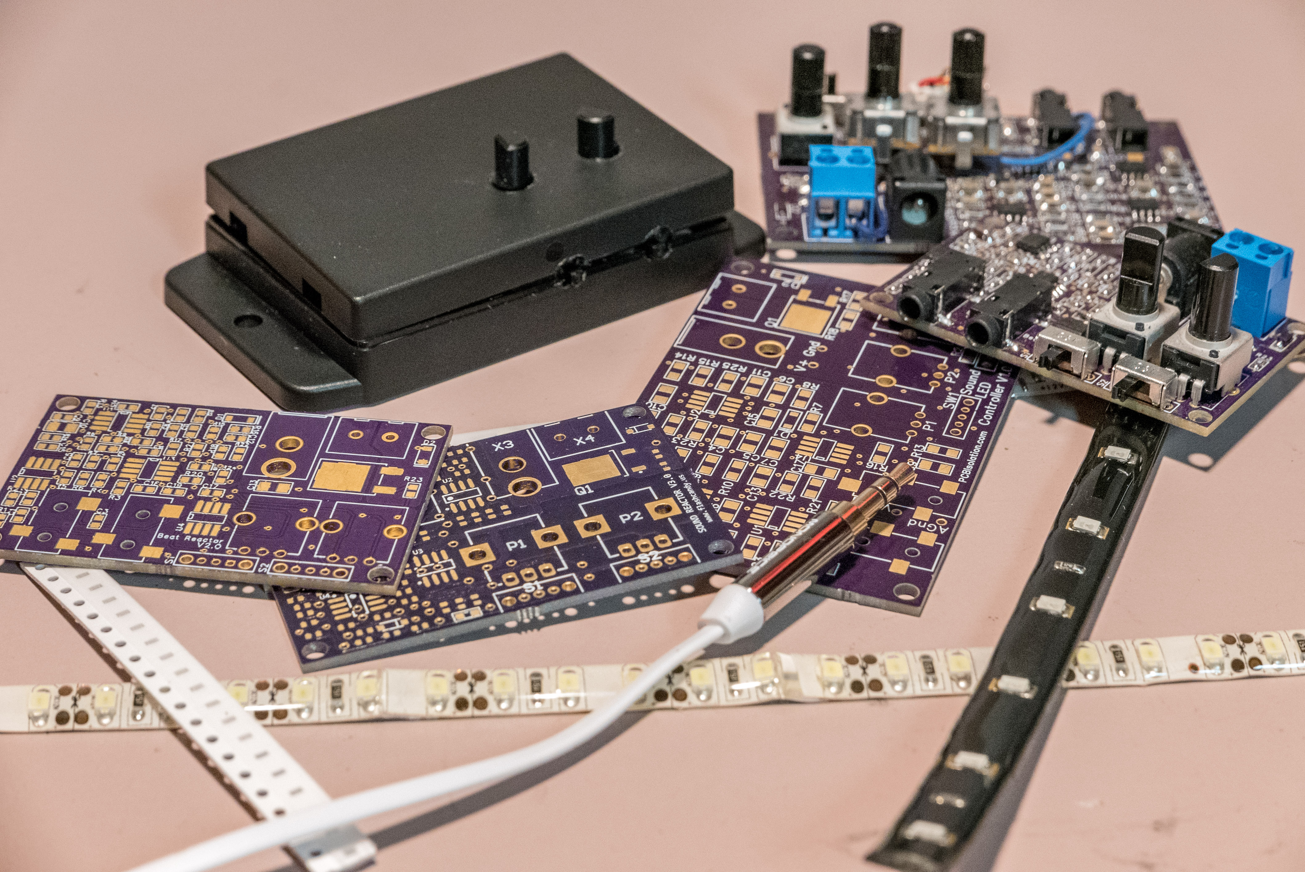
What It Does
There are two modes to the Sound Reactor. First, it acts as simple dimmer. You turn a knob to adjust brightness.
Flip a switch and it becomes a sound reactive dimmer. The first knob adjusts the brightness when there is no bass. The second knob adjusts the sensitivity – how much brighter the lights get to the music.
A final switch determines whether the lights get brighter or dimmer upon the bass hit.
Design – It’s Not All Analog
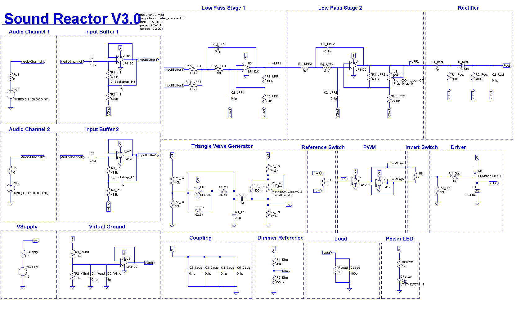
My circuit uses 8 op-amps and no digital circuitry.
Stereo audio comes through a set of high-impedance buffers. This is traditionally done with an expensive instrumentation amplifier. I opted for a cheaper and still effective bootstrap design. The input impedance is brought into the megaohm level, to reduce load on the audio source.
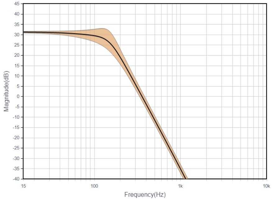
Next, we sum both signals into a 4-pole low-pass butterworth. I used Analog Device’s Filter Wizard for this section. 32dB of gain, f3dB at 150Hz, and -50dB at 1kHz. See the response below.
Frequency Response (dB)
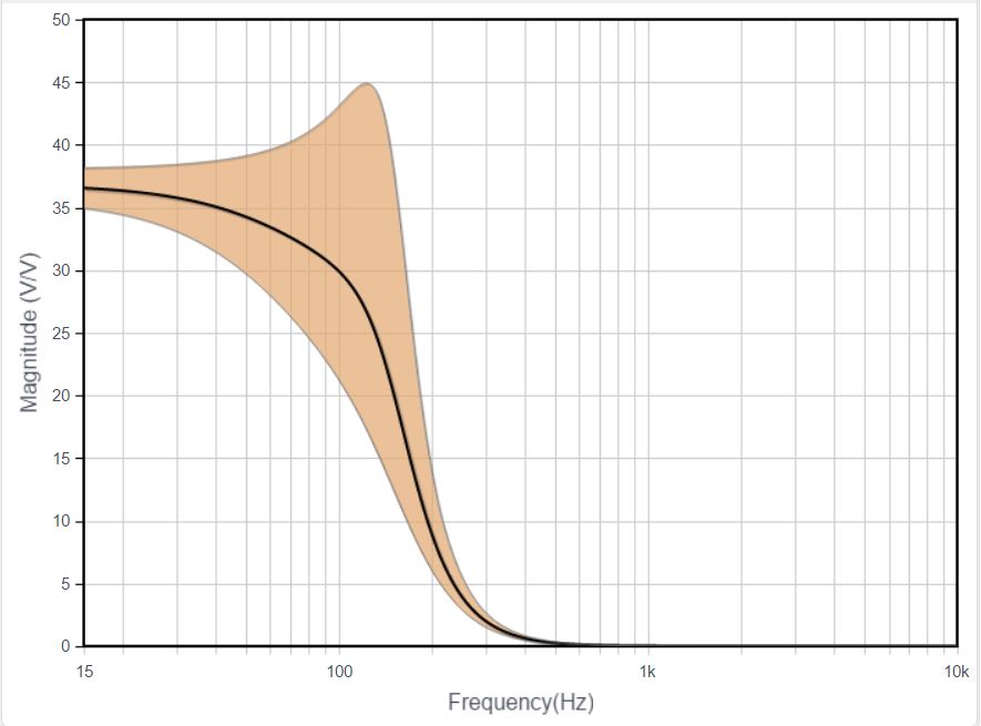
Frequency Response (V/V)
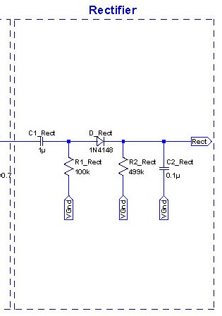
So far, we have a buffered, amplified AC signal. I want to convert this into a useable signal, a voltage that show the average intensity. Look at the rectifier circuit below. It’s a peak detector, tuned to have a good decay for signals as low as 20Hz.
The rectified signal is sent to an op-amp acting as a comparator. On the other input of the comparator is a triangle wave generator. This is what produces the PWM output. But where does the triangle wave come from?
Triangle Wave Generator
This triangle wave generator uses a single op-amp – not a common design. Most triangle wave generators use two op amps. One generates a square wave and the other integrates it, producing a triangle wave. Click here for a two op-amp design.
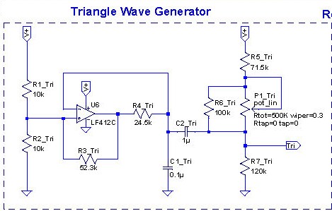
In short, positive feedback with hysteresis causes the output to continuously saturate. I’ll detail the specifics in a later post.
On the right side, you can see the output goes through a voltage divider with a pot. This allows us to adjust the center point of the signal (think of moving a triangle wave up and down on the y-axis of an oscilloscope).
PWM and Output Driver
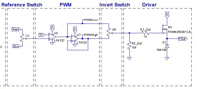
This is the final stage. U2 is the op-amp acting as a comparator. When a triangle wave is compared against a signal, it generates a PWM output (see figure below).
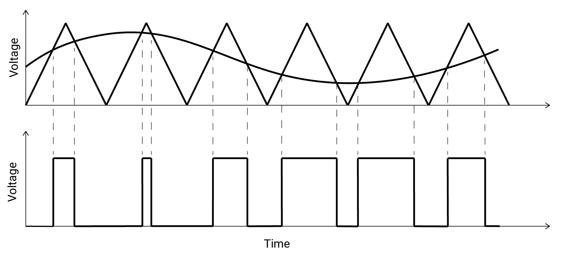
Brightness is adjusted by moving the triangle wave above or below the audio signal. This is what the output voltage divider and potentiometer in the triangle wave generator are responsible for. The gain of the audio input is responsible for the sensitivity – how much the lighting changes from a bass hit.
To summarize, the two knobs (one for gain and one for DC bias) are used to adjust PWM output to the user’s liking.
U7 is an inverter. U2 and U7 feed straight into a switch (looks like a potentiometer in the diagram). This switch is for inverting the PWM output. Visually, the LEDs get brighter on the bass hit. Flip the switch and they get dimmer on the bass hit.
The PWM signal then feeds into a MOSFET to drive the LEDs.
Virtual Ground
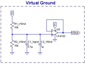
The Sound Reactor is powered by 12V DC. The virtual ground is at VCC/2 or 6V. I need a virtual ground for operating op-amps from a single supply.
The virtual ground is used for the input buffers and low pass filter.
Designing the Board
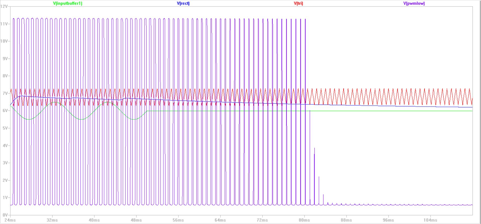
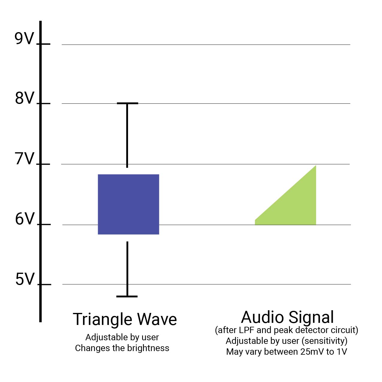
The schematic design and simulation was in LTSpice. Above is an example simulation output. The green signal is a 100Hz tone. The blue signal is the audio input after a LPF and peak detector. The blue signal is compared to the red triangle wave, generating the purple PWM output. The PWM increases duty cycle when the bass note hits, then decays down after ~30ms.
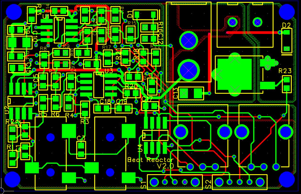
For versions 1 and 2, I designed the PCB in FreePCB. Afterwards, I learned there are better free alternatives available (KiCad and CircuitMaker by Altium) so I don’t recommend using FreePCB. Additionally, importing a circuit from LTSpice to FreePCB is tedious.

For the third and final version, I switched to CircuitMaker. It is Altium’s free version of Altium Designer designed for hobbyists and DIY. CircuitMaker is very similar to Altium, it feels like a stripped down, simpler version.
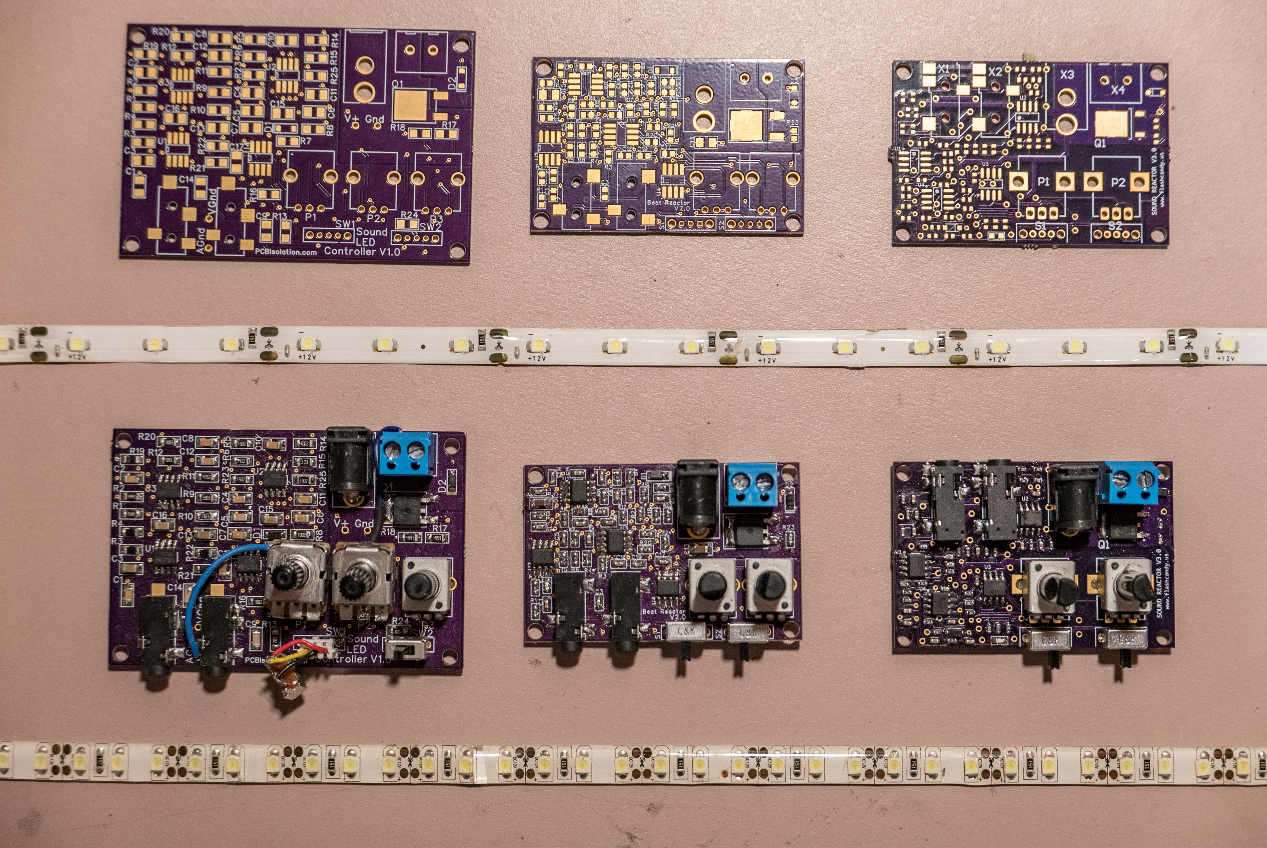
Version 2 changes:
- SMD components changed from 1210 to 0603
- Simplify design (removed extra potentiometer)
- Change LPF characteristics for stability
- Increase PWM speed to 1kHz
- Add coupling caps
- Lengthen decay time of peak detector
- Increase input impedance of peak detector
Version 3 changes:
- Move audio connectors to rear of board
- Reduce unique part count
- Add power led indicator
- Change audio from 3 pin to 4 pin connectors
- Redesign triangle and PWM section for stability
- Linearize adjusts of potentiometers
- Double gain of LPF
Why I Failed
- The fundamental problem is the all analog approach. I thought it’d be simpler, but look at schematics. It’s not simple. High unique part count. 4 dual op-amps costs nearly as much as a microcontroller. The potentiometers could be replaced with buttons in a digital design, lowering the cost further.
And further, it’s really not all analog. I’m using analog components to simulate a digital function – PWM. Hell, I’m driving a discrete digital devices – Light Emitting Diodes. - It only drives single color LEDs. To drive RGB LEDs, I’d need to nearly triple the components. In a digital design, it’d only be an extra output from the microcontroller. So it doesn’t scale well either.
- My circuit pushes the limits of the op-amps. The low pass filter is aggressive, especially with the high gain on the final stage. Due to part tolerance, some boards may have higher gain than other. So sometimes, the op-amps saturate when the gain is too high. I could not design for great response, a wide range of adjustability, and low cost. Pick two!