(ordered by newest projects first)
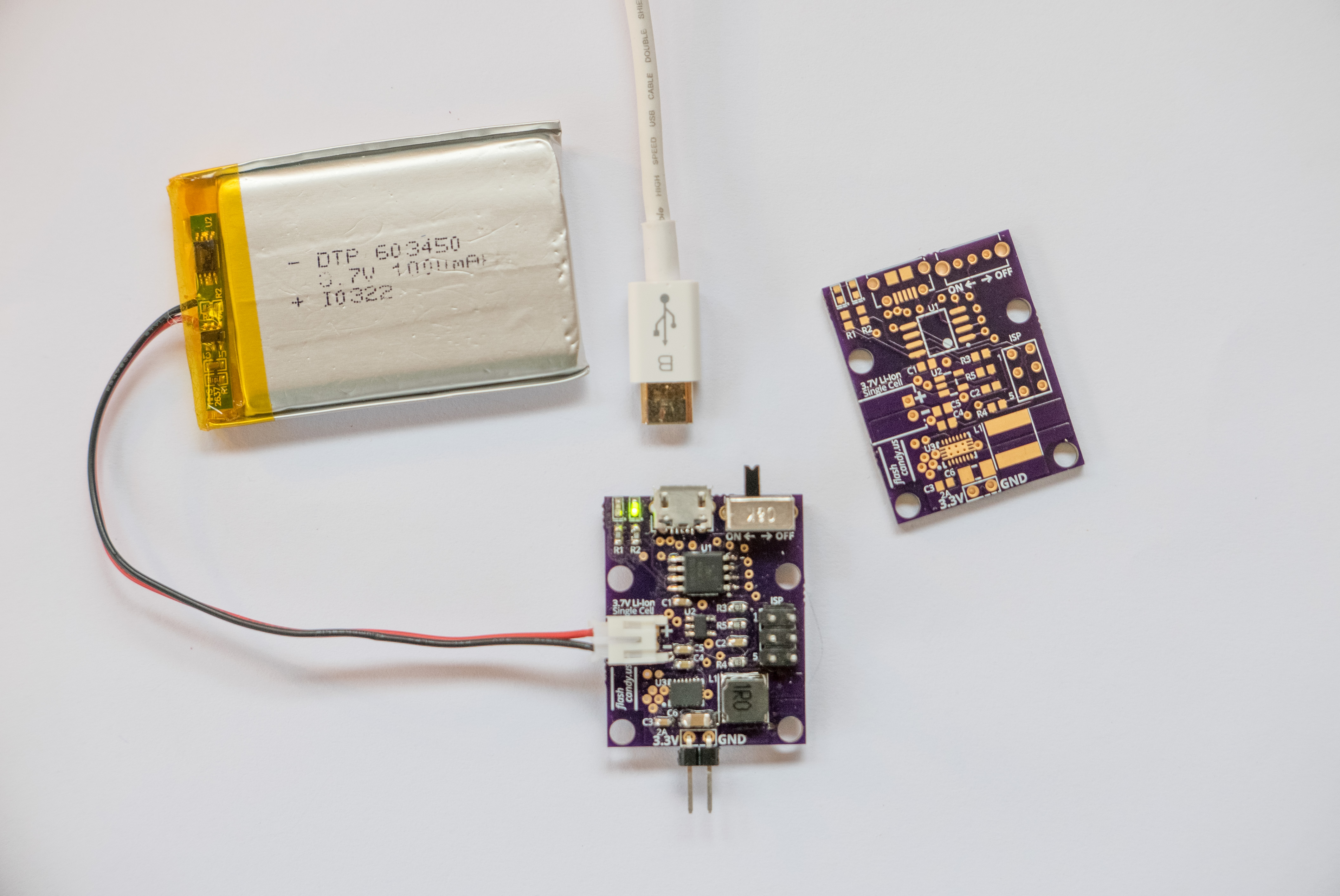
Little Nugget v2 - 5V 2A Power Supply
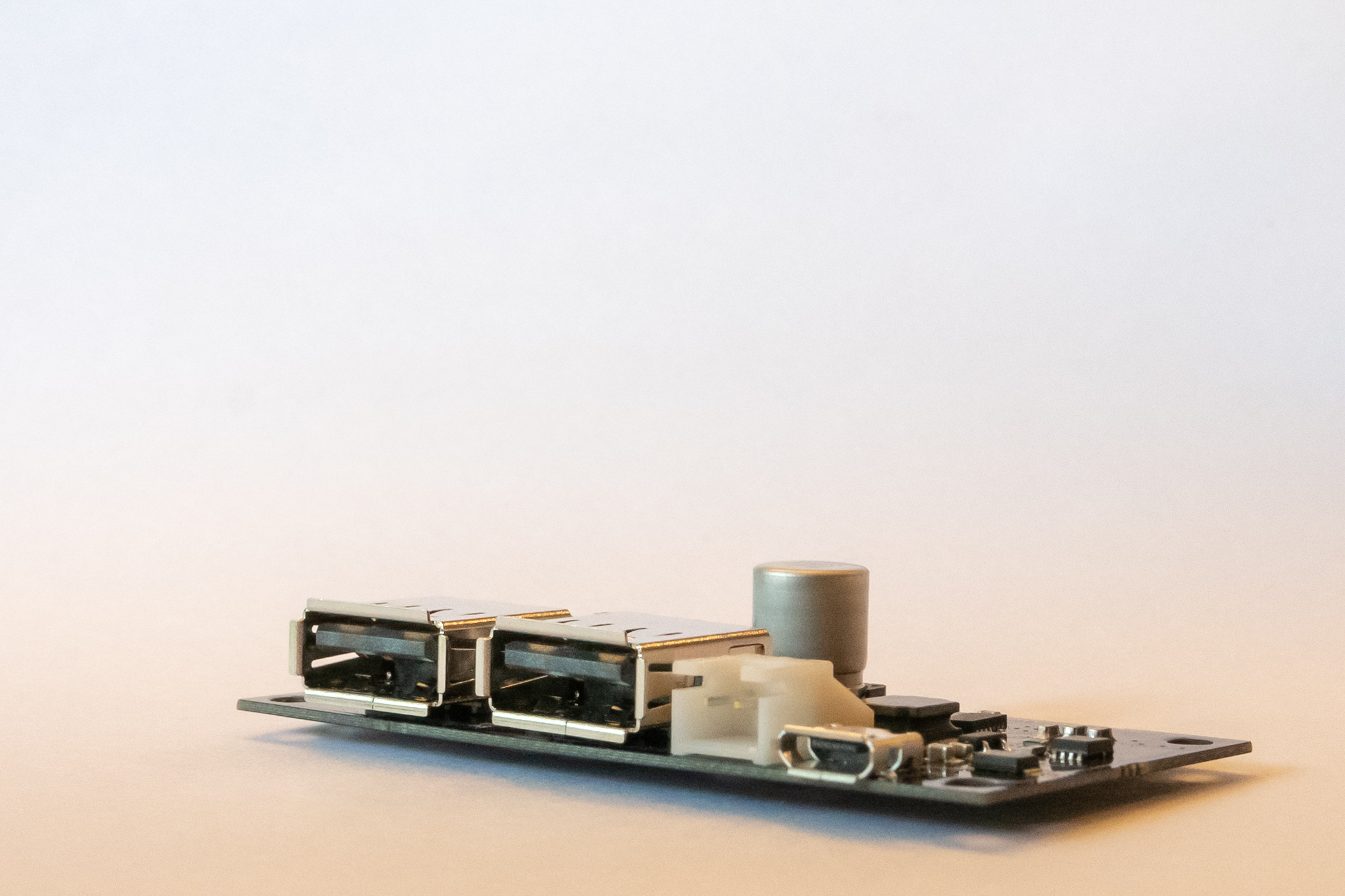
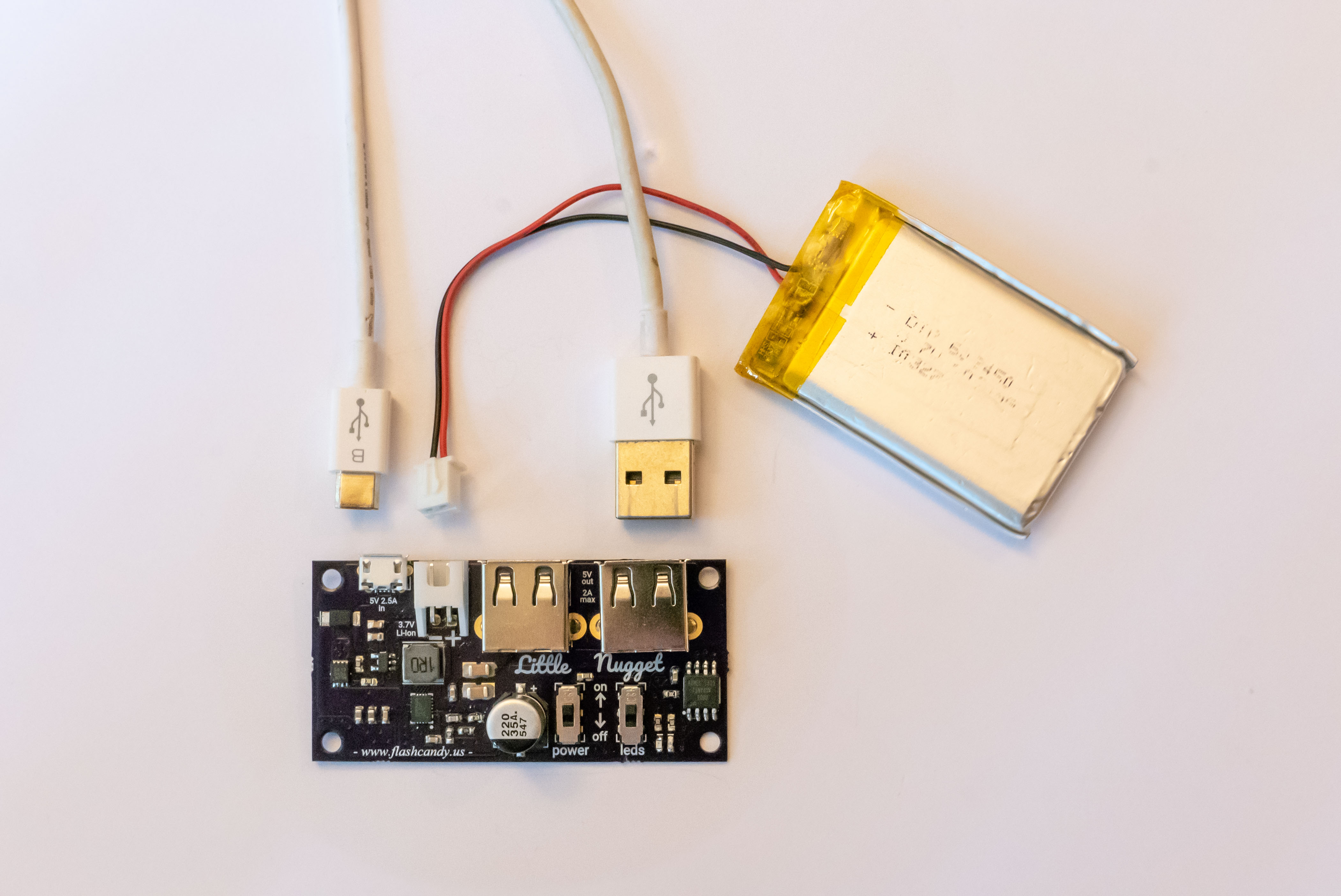
This 5 Volt 2 Amp power supply runs off a single Li-Ion cell and is charged via micro USB. It has 2 USB type A outputs.
The input can provide power to the output and charge the battery simultaneously. When the input power is removed, the battery supplies power to the output.
An ATtiny45 microcontroller handles power management. There are two LED indicators for status and battery charge level.
At idle, the board draws less than 2μA!
More details are available at www.flashcandy.us/products/little-nugget-v2
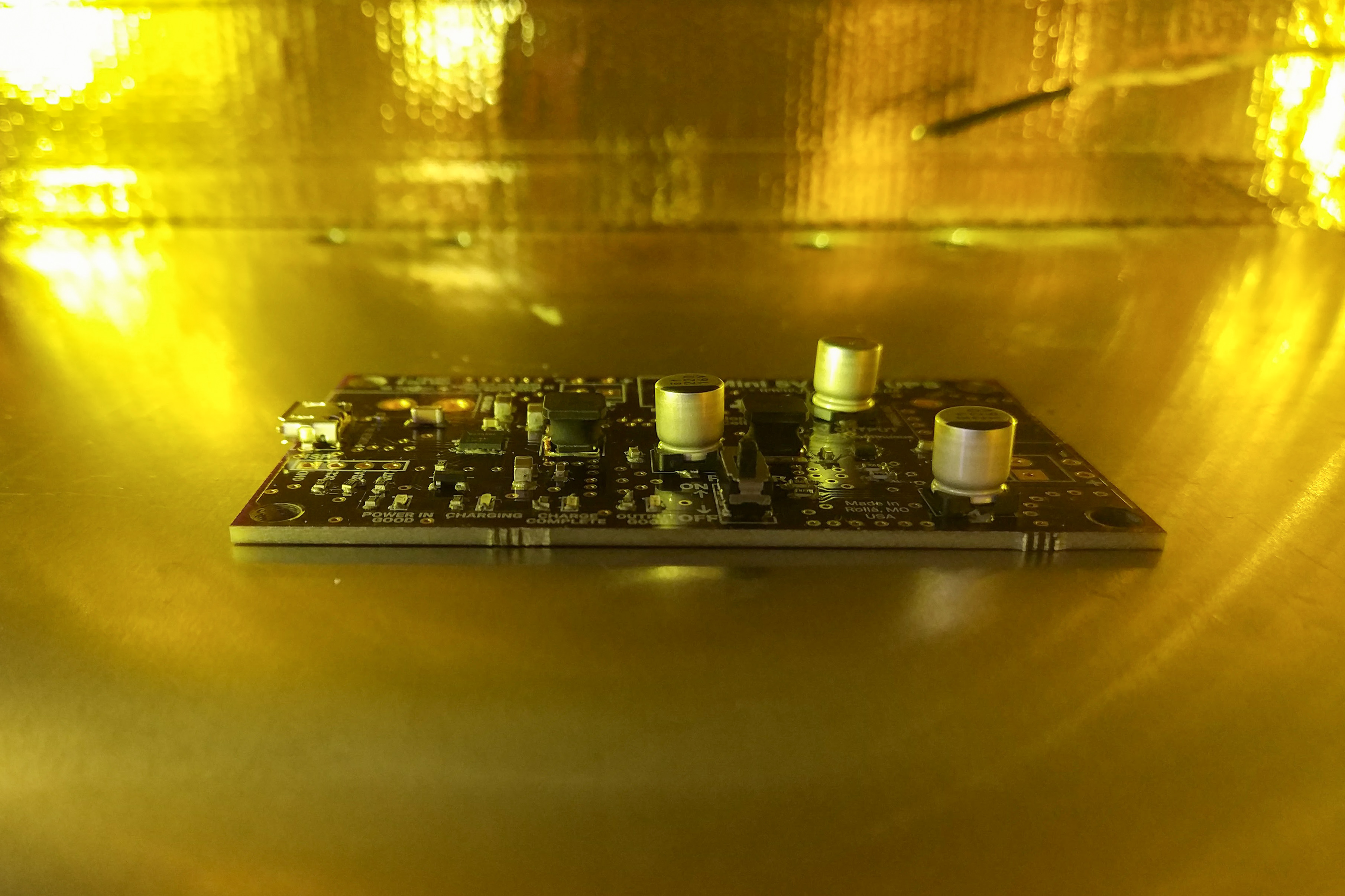
Big Nugget v2 - 5V 4A Power Supply
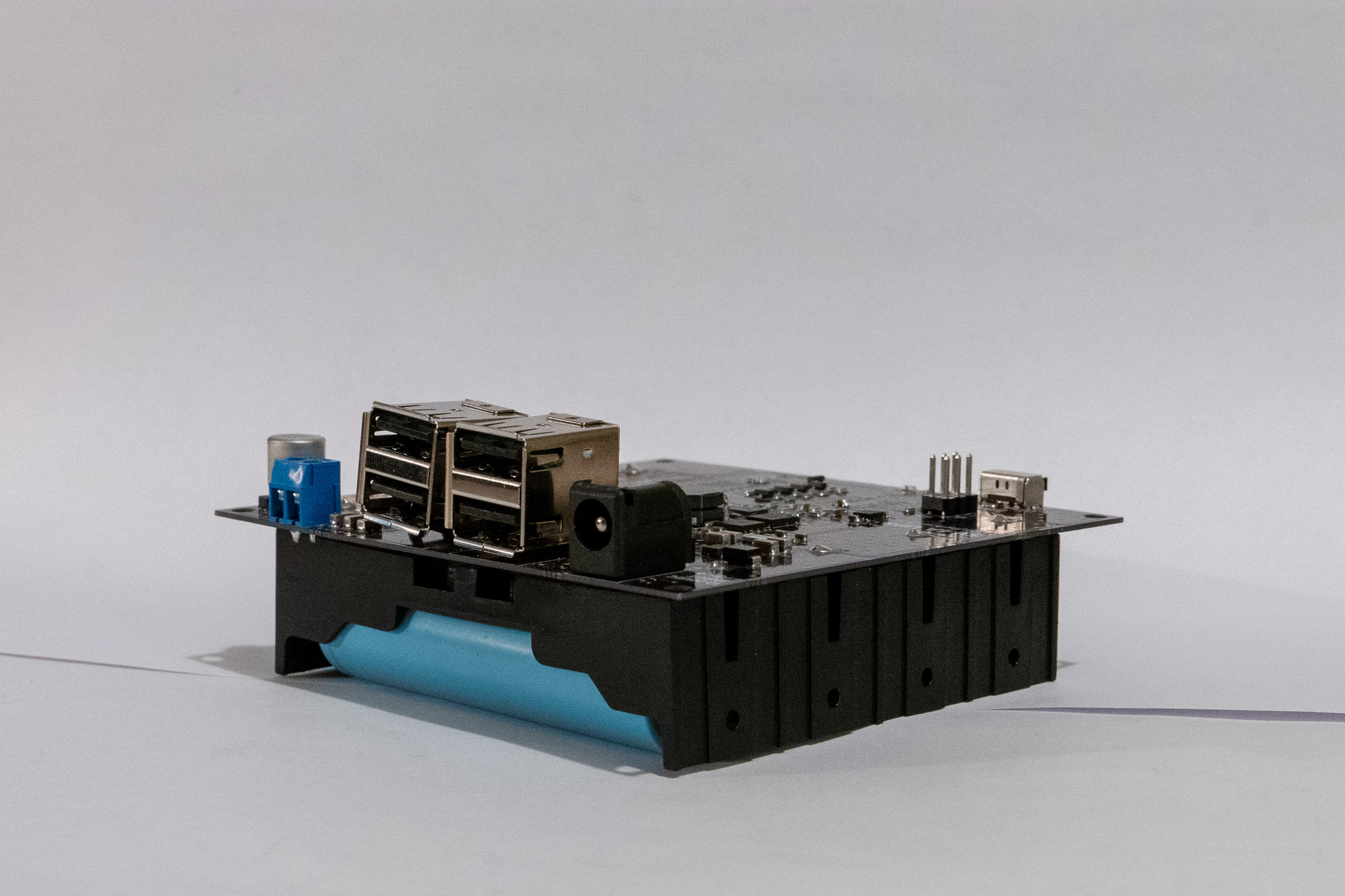
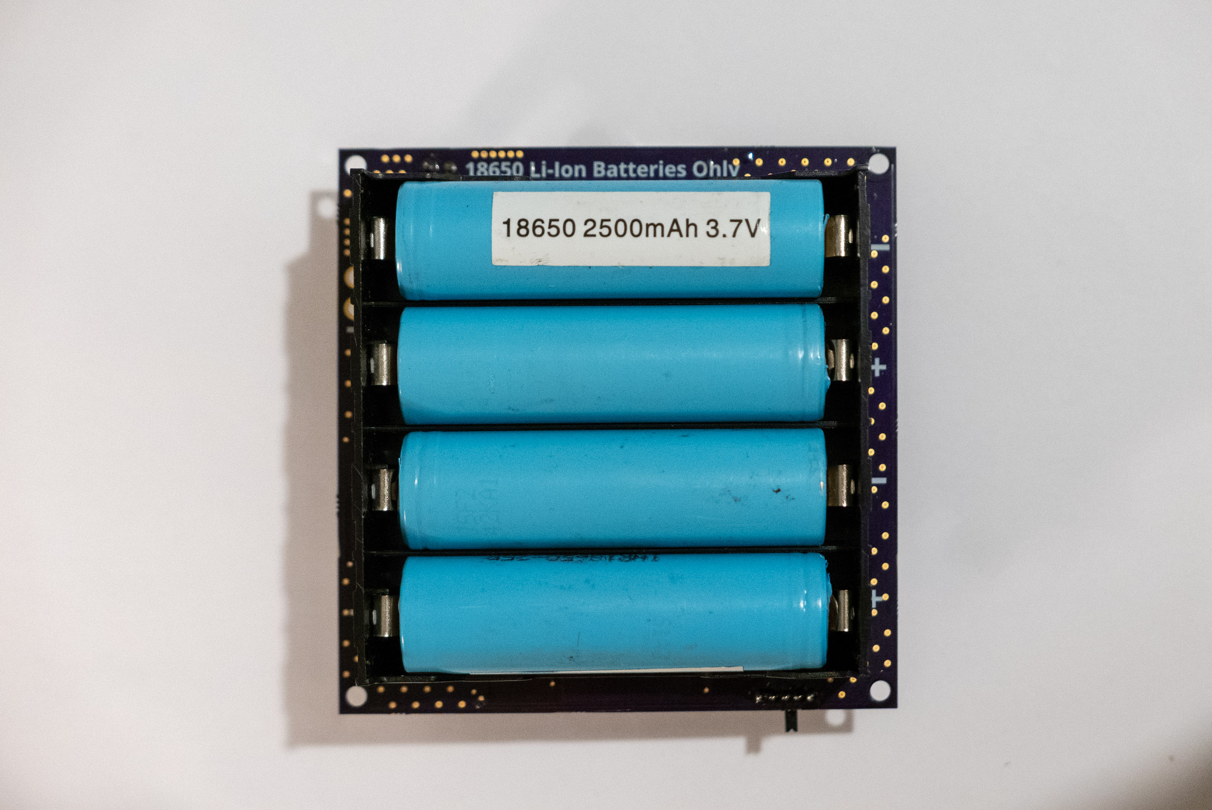
The Big Nugget is best for high current projects needing long runtime from a battery source. It’s great for Raspberry Pi, BeagleBone, Arduino, IoT, and more.
It can power a Raspberry Pi drawing 1A for about 7 hours. An optional header allows you to connect larger batteries for extended runtime.
The input can provide power to the output and charge the battery simultaneously. When the input power is removed, the battery supplies power to the output.
I2C is available for checking battery capacity and voltage. It can also be used for adjusting settings such as max charge rate and input current limit.
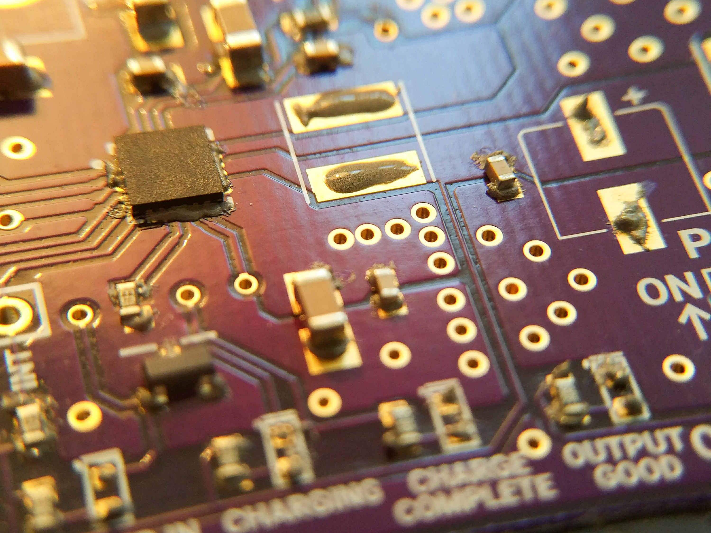
The Big Nugget v2 is based on the Texas Instruments BQ25703A power management IC and the AOS AOZ2261 buck regulator.
Specs:
- 5VDC Output
- 4A Max continuous output
- Adjustable battery charge rate (5A max)
- 9V - 20V input
- 60μA sleep current
- Custom 4 cell BMS and balancing
- Optional headers for connecting larger batteries
More details are available at www.flashcandy.us/products/big-nugget-v2
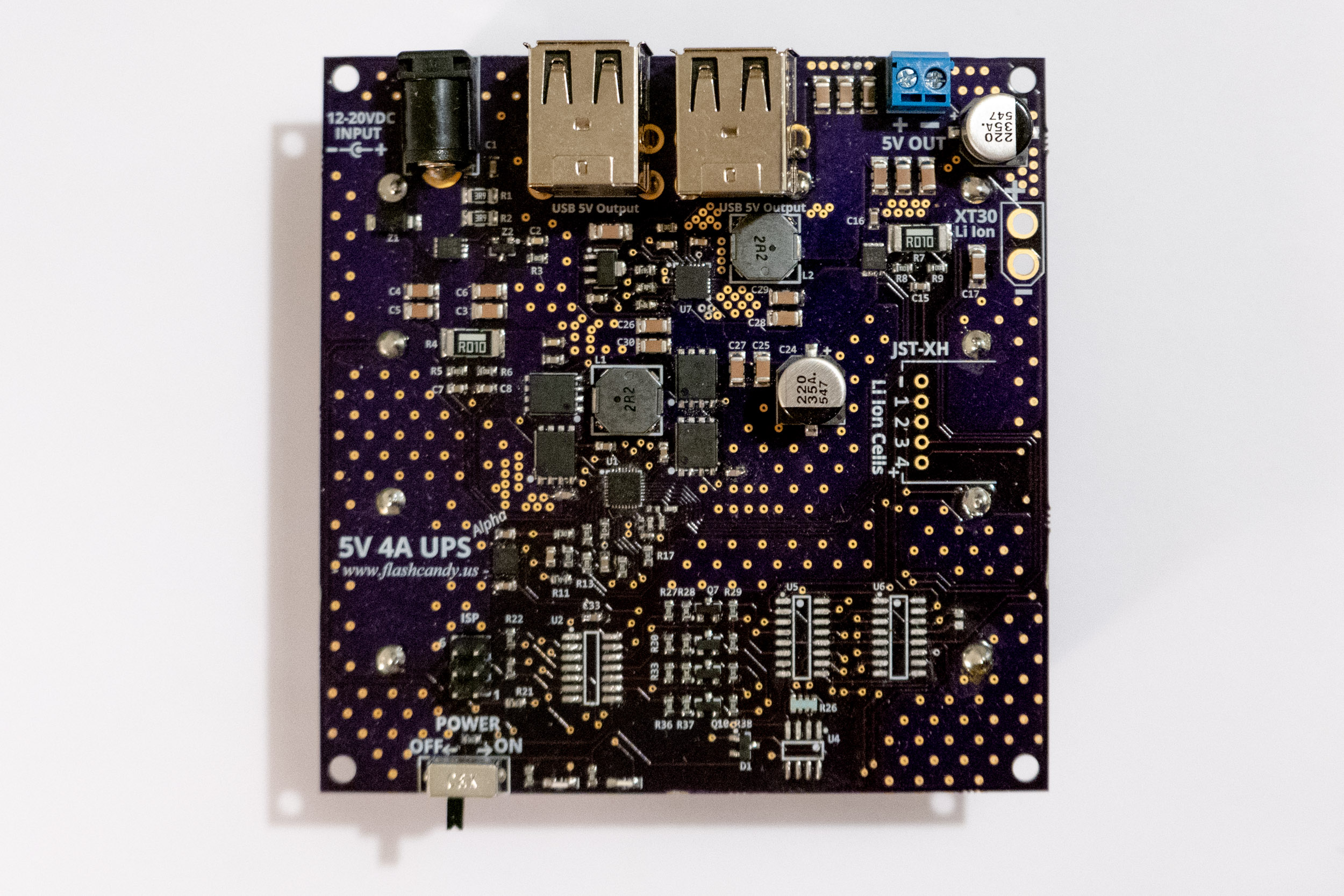
Big Nugget v1 - 5V 3.5A Power Supply
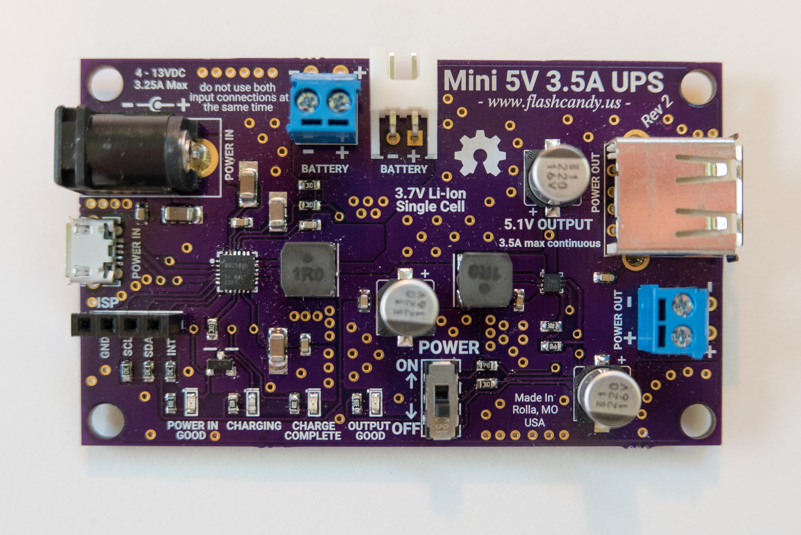
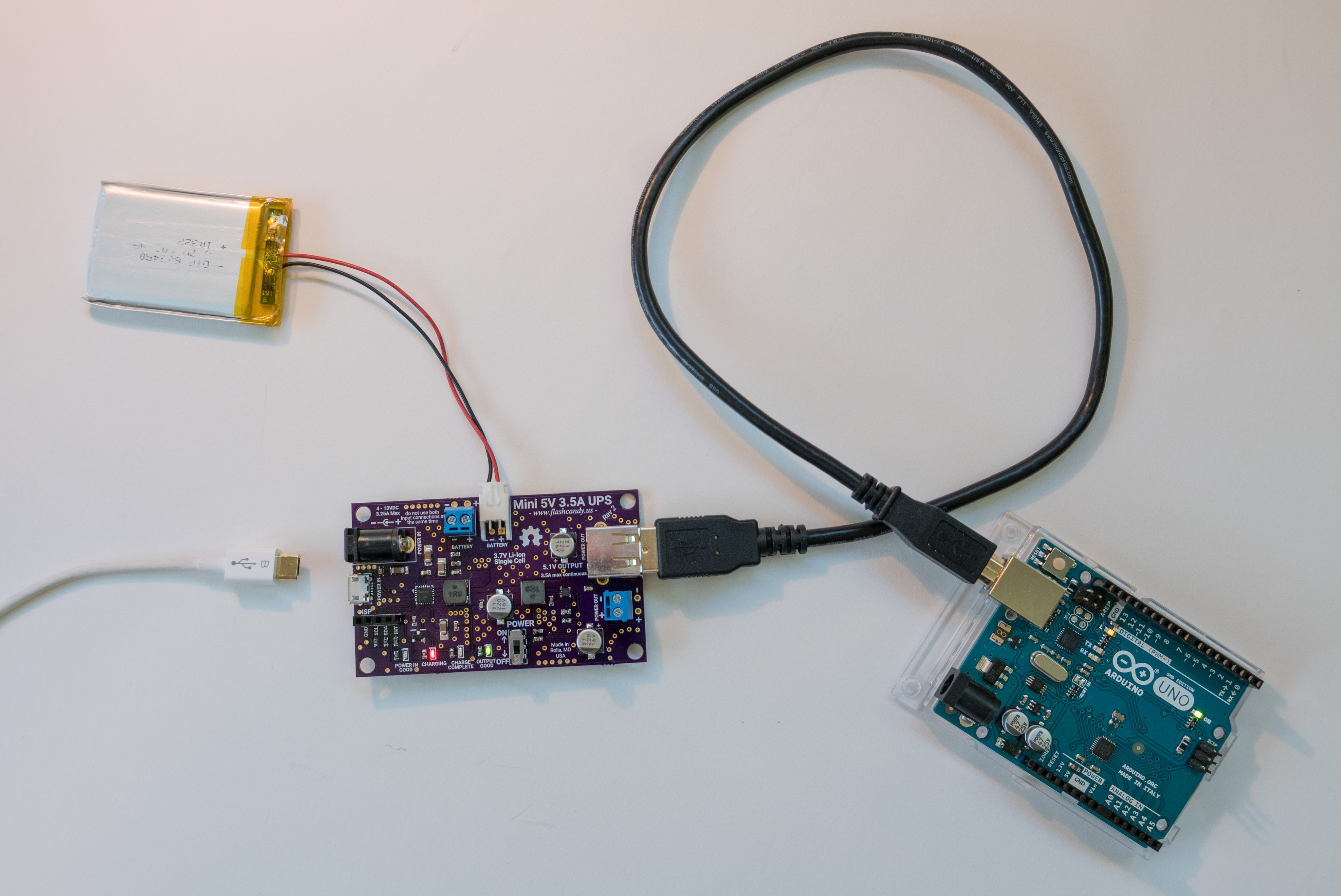
This is the first version of the Big Nugget. Version 2 improves considerably on this design. Compared to version 2, this has a single cell battery, 2 USB type A outputs, and a different set of power management ICs.
The microUSB input can negotiate from 100mA to 3.25A with USB MaxCharge and High Voltage Adapters.
The Big Nugget v1 is based on the Texas Instruments BQ25895 power management IC and the Microchip MIC2876 boost IC.
Specs:
- 5VDC Output
- 3.5A Max continuous output
- Adjustable battery charge rate (5A max)
- 9V - 20V input
- 50μA sleep current
The board and design files are available at www.flashcandy.us/products/big-nugget-v1
Little Nugget v1 - 1.8v/3.3V/5v 2A Power Supply
This 5 Volt 2 Amp power supply runs off a single Li-Ion cell and is charged via micro USB. There are 3 versions of this power supply - 1.8V, 3.3V, and 5V output.
This board requires a battery to operate. Version 2 improves on this - it operates with or without a battery installed.
An ATtiny45 microcontroller handles power management. There are two LED indicators for status and battery charge level.
At idle, the board draws less than 2μA!
The boards and design files are available at www.flashcandy.us/products/little-nugget-v1
Reflow Toaster Oven
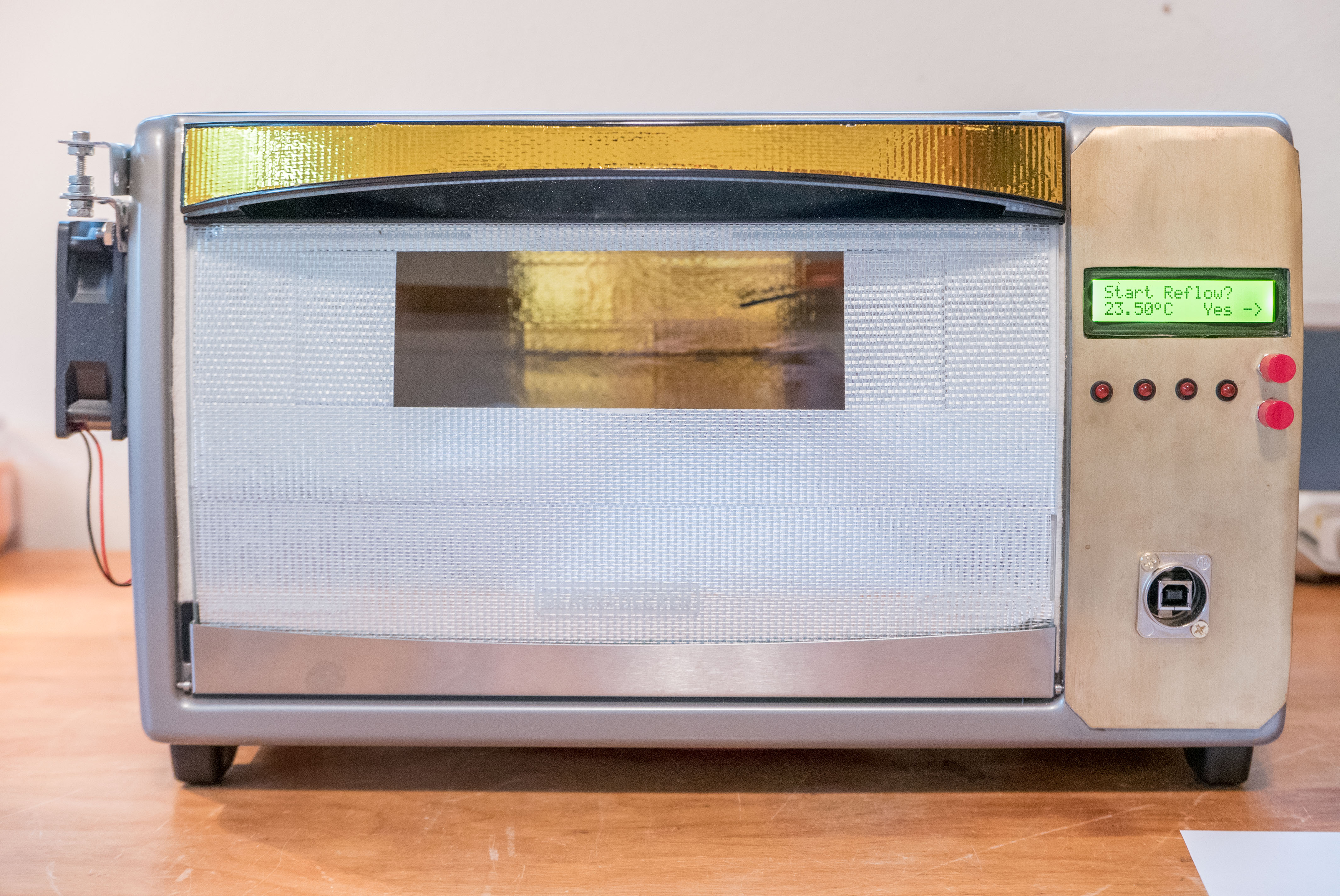
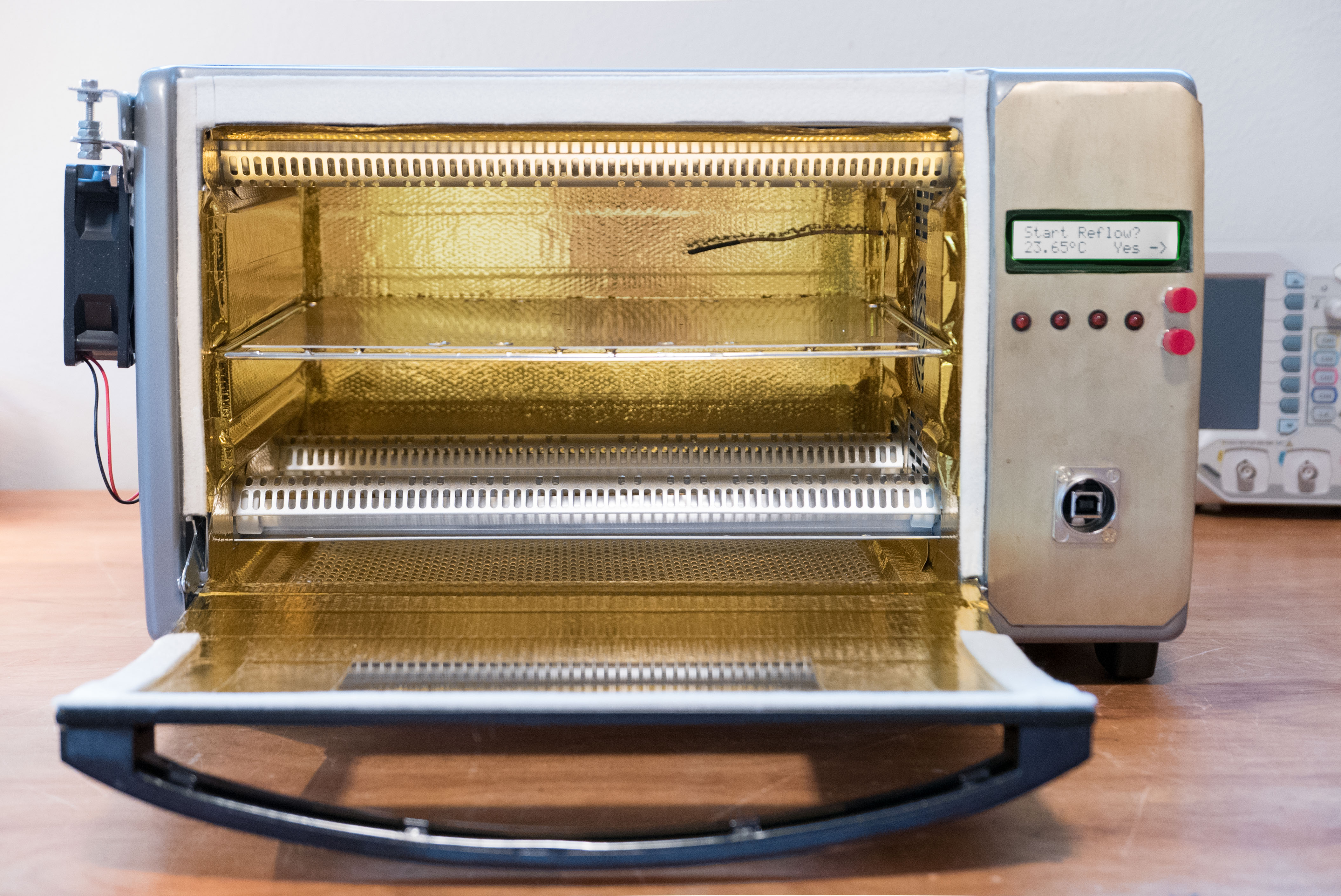
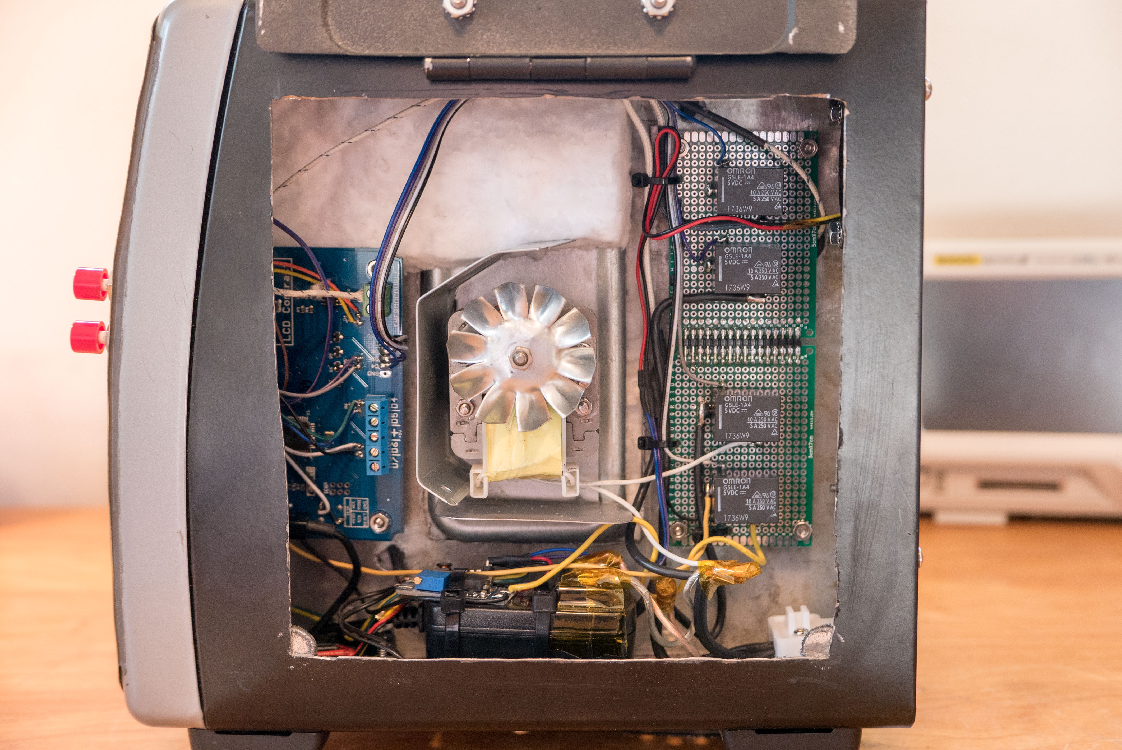
This is my retrofitted Black and Decker toaster oven for reflow soldering. To reduce the temperature gradient, the unit is insulated with 1″ ceramic blanket, Reflect-a-Gold tape, door sealant, and Boom Mat.
The controller is the popular ControlLeo2. A fan is used to improve the cooling speed. A temperature sensor and independent top and bottom heaters provide a consistent and accurate reflow profile.
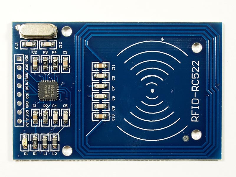
MFRC522 RFID Reader and Writer
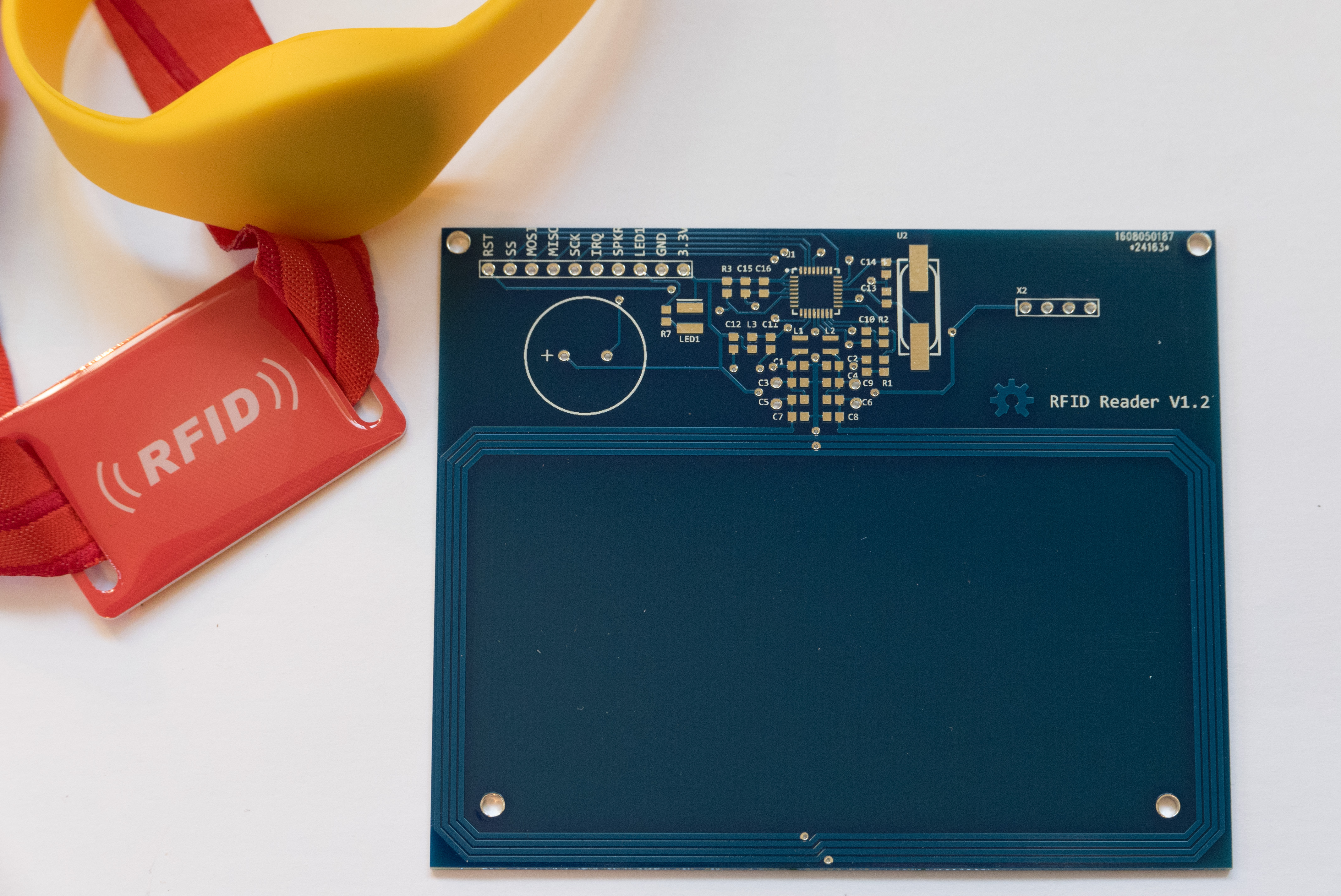
This RFID board uses NXP’s MFRC522 RFID chip. It’s an excellent chip, but the only development boards currently available are poor quality and poor design (see example here).
I designed this as a high quality alternative. It uses a much larger board and more components, but the increase in read/write range is phenomenal! You can find my design files here.
ZigBee Mesh Node
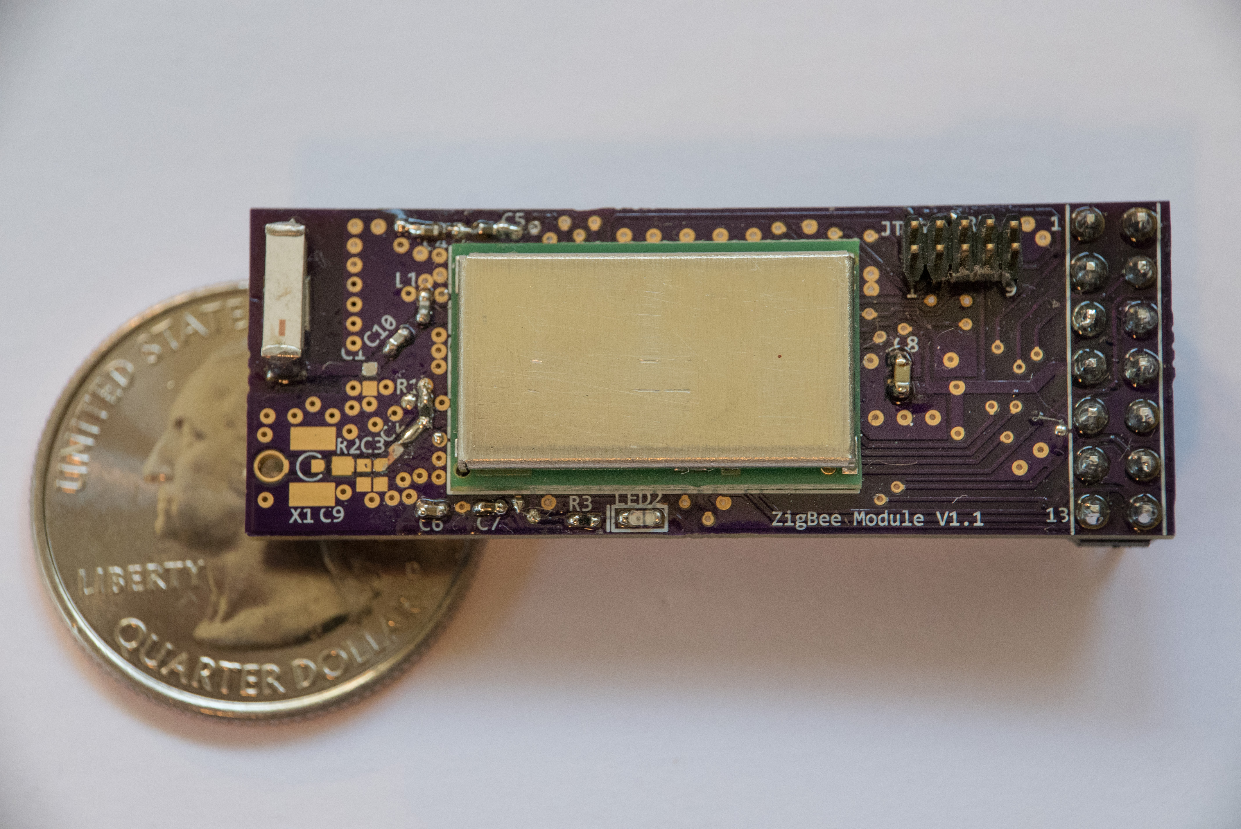
This board is for a node within a mesh of ZigBee hubs, ideally for an Internet of Things application.
I used the Atmel ATmega256RFR2, an ATmega with a RF front-end designed for 2.4GHz communication. The main module is the Dresden Elektronik deRFmega256. I chose this module because of its low cost, antenna diversity, power amp, and FCC certification. The design is based on the Dresden Elektronik FCC Compliant reference design.
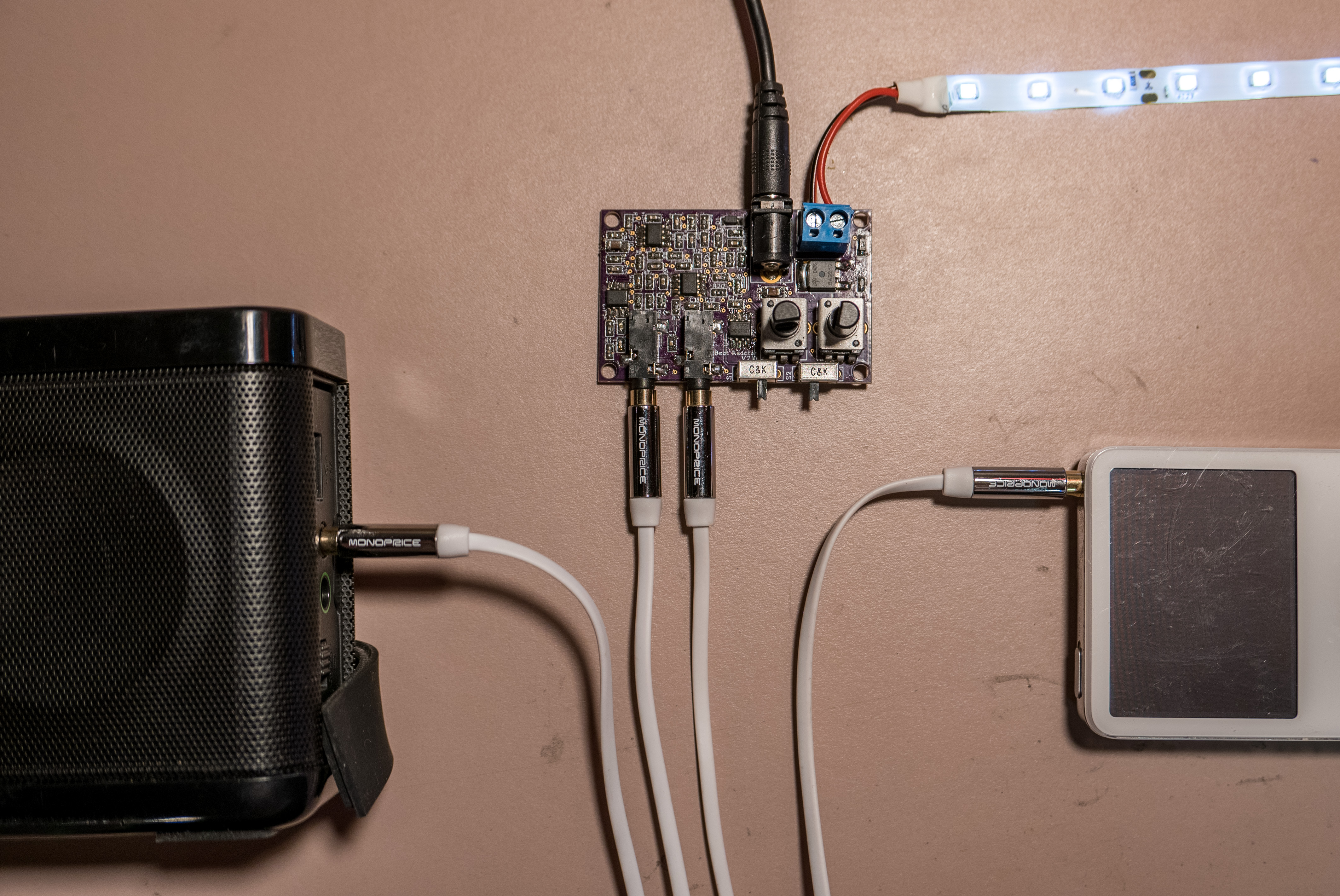
LED Sound Reactor
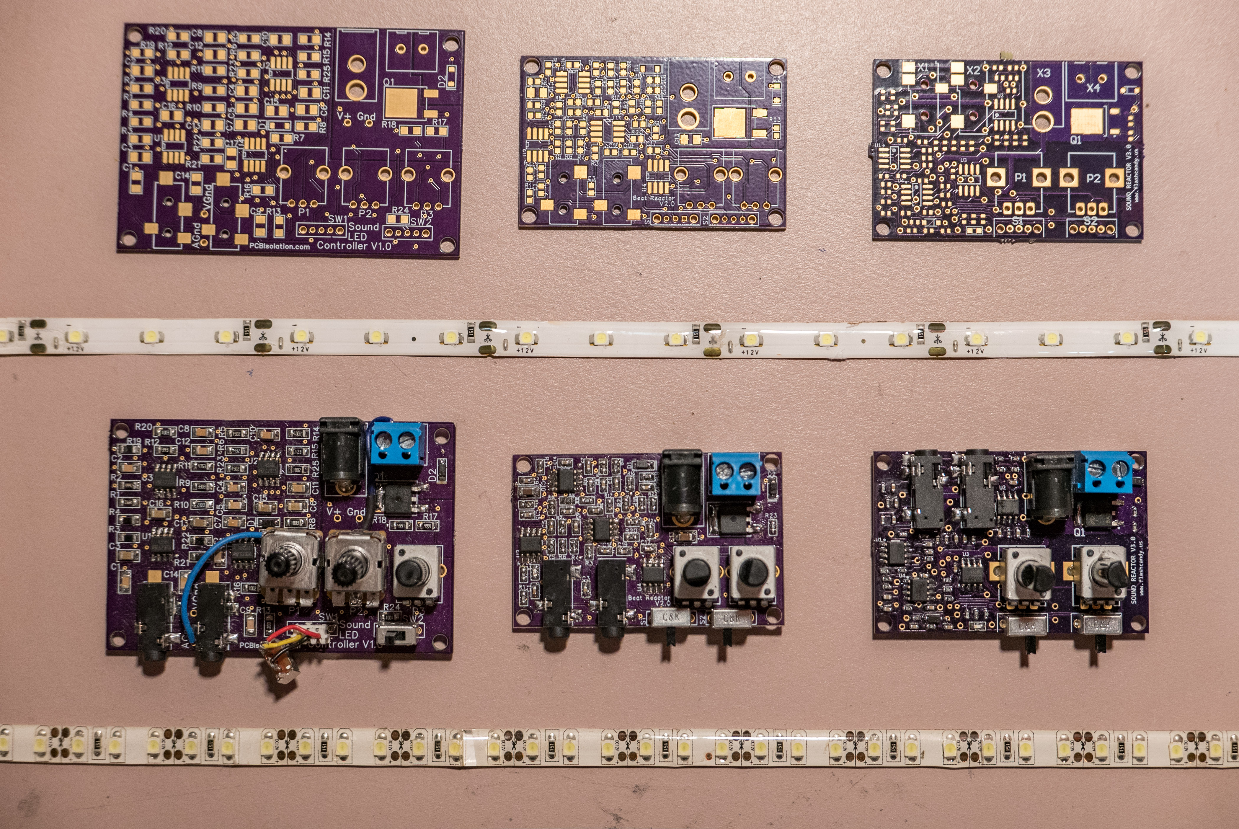
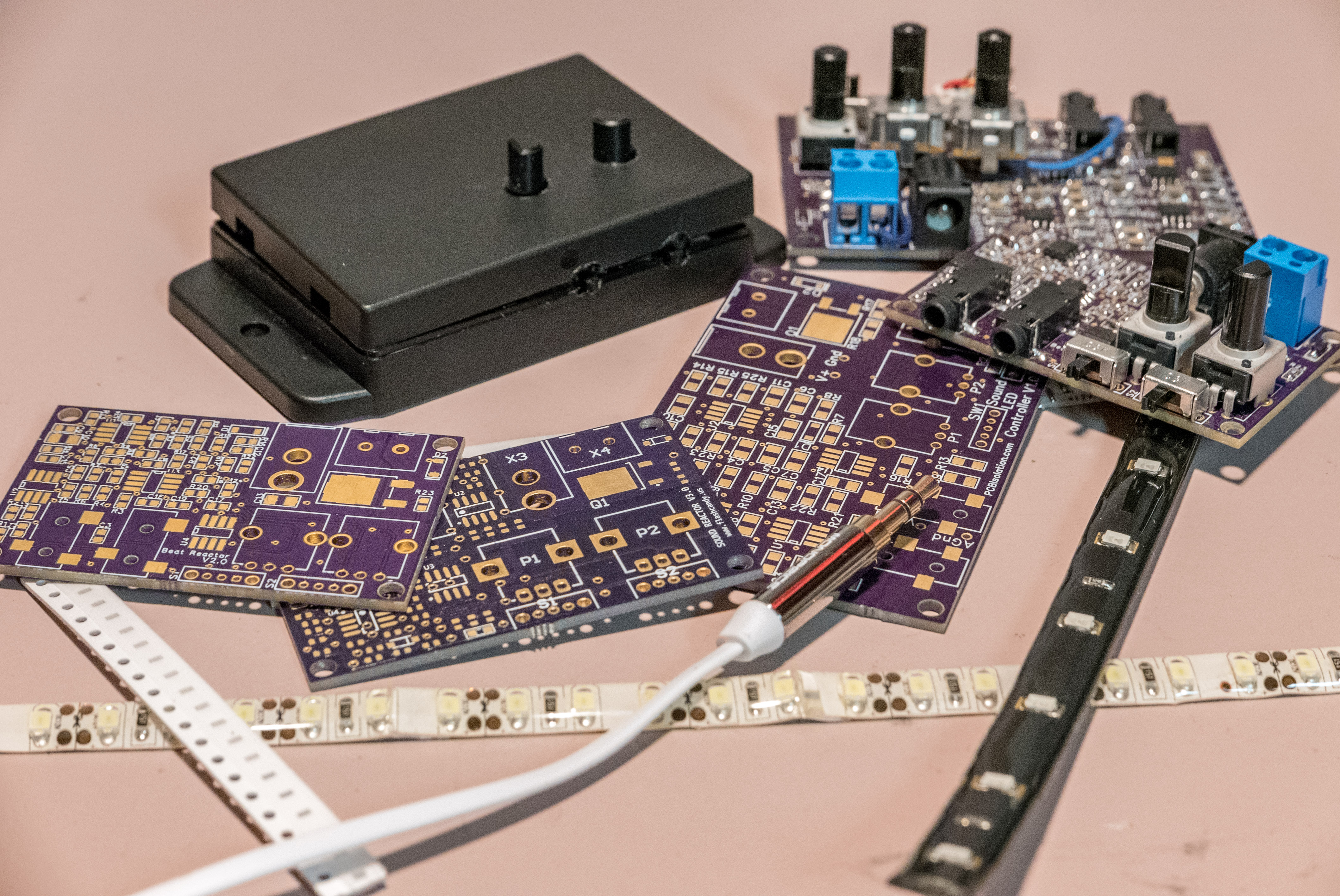
This is an LED controller for fans of music. You plug in LED lights and a power source. Turn the first knob and the device acts as a simple light dimmer.
Now add a music source. The lights will react to the bass of the song (pulsing with the beat). You can adjust how sensitive the lights are to the music and more with the control knobs.
The design is entirely analog. It uses 8 op-amps and many discrete components. I found there were plenty of shortcomings to this design, particularly for scalability. Read more here.
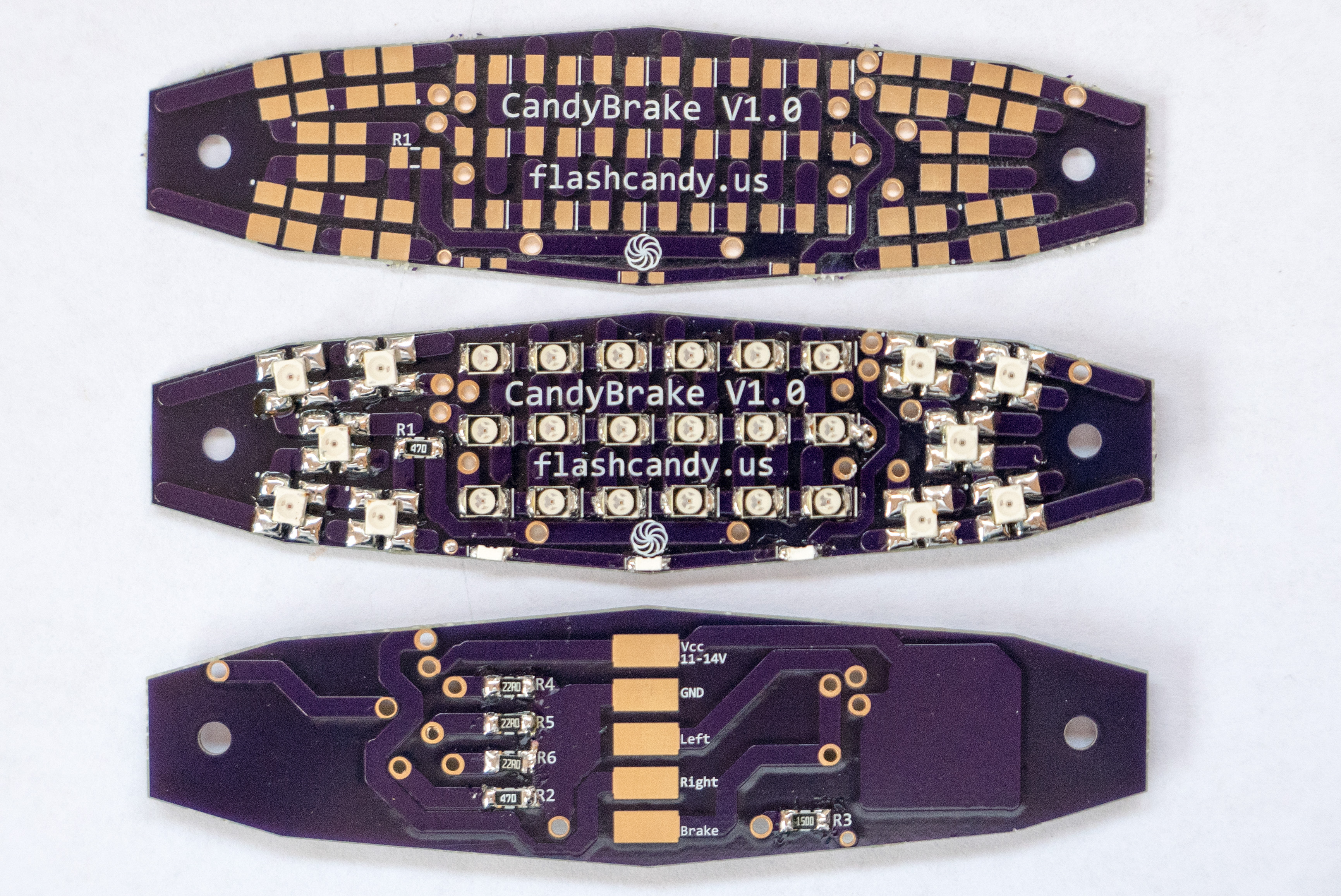
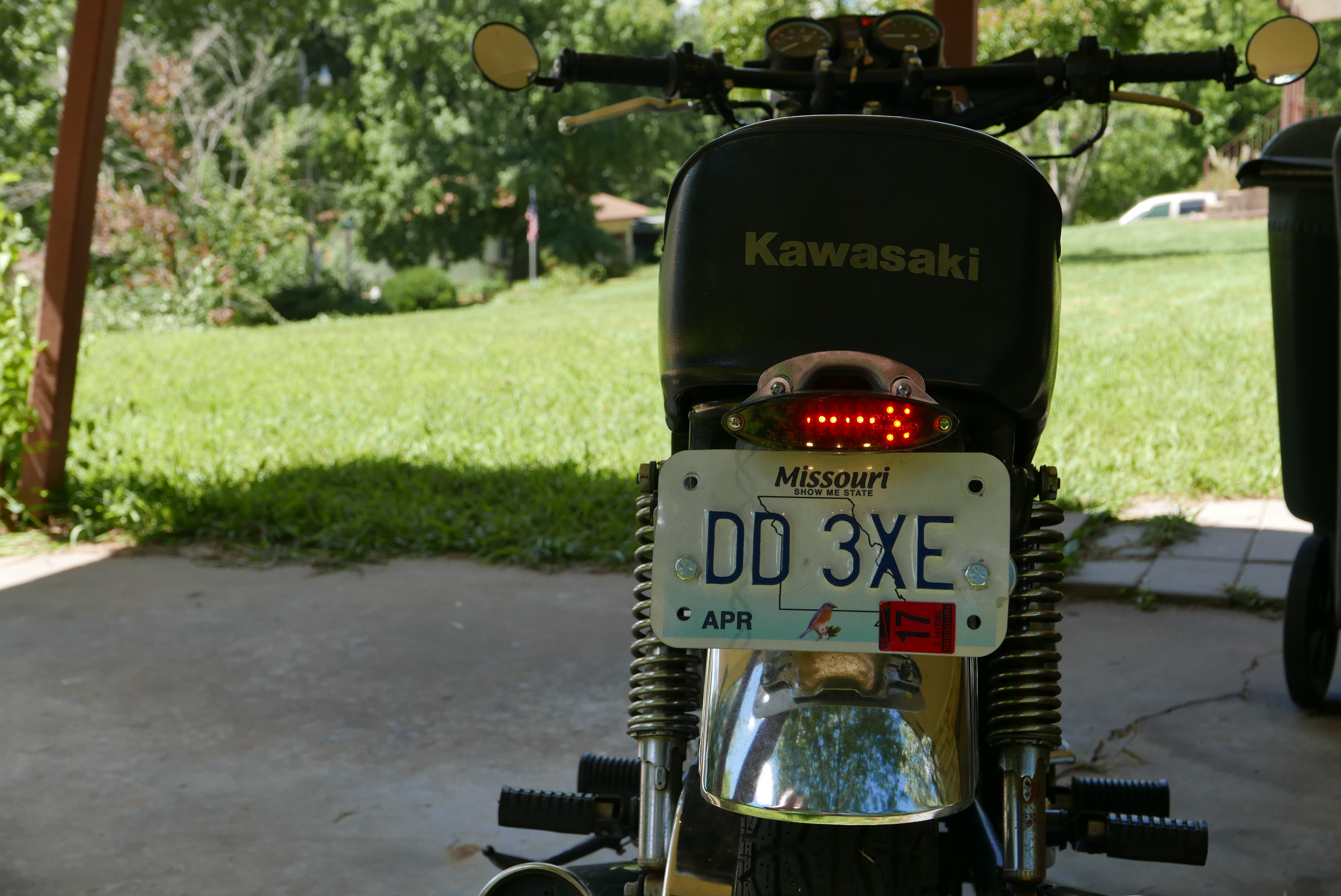
Motorcycle Brake and Turn Light
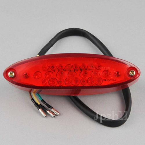
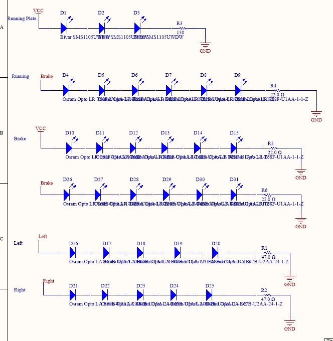
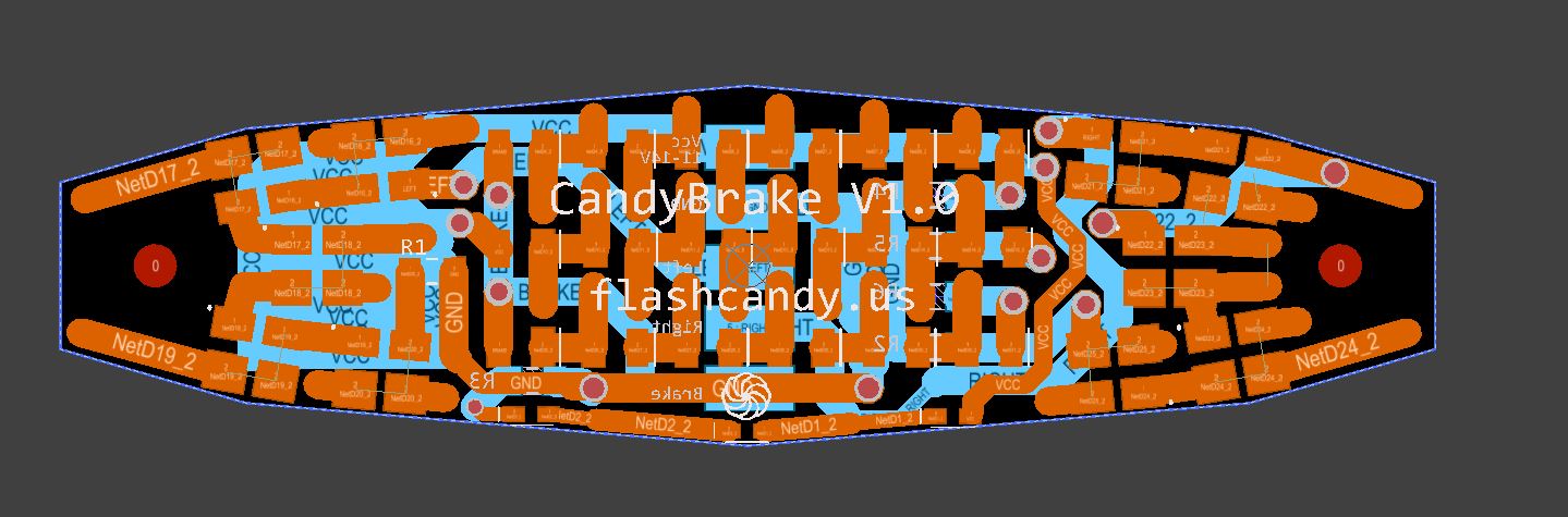
I was unsatisfied with the brake and turn signal combos available online, so I made my own. It has running lights, brake lights, turn signals, and license plate illumination. I used high output LEDs and used the extra space on the PCB for heat sinking.
If you’re curious about the bike, it’s a 1983 Kawasaki CSR 305. Here’s a picture of it next to the Mississippi River.
More details about the brake light here.
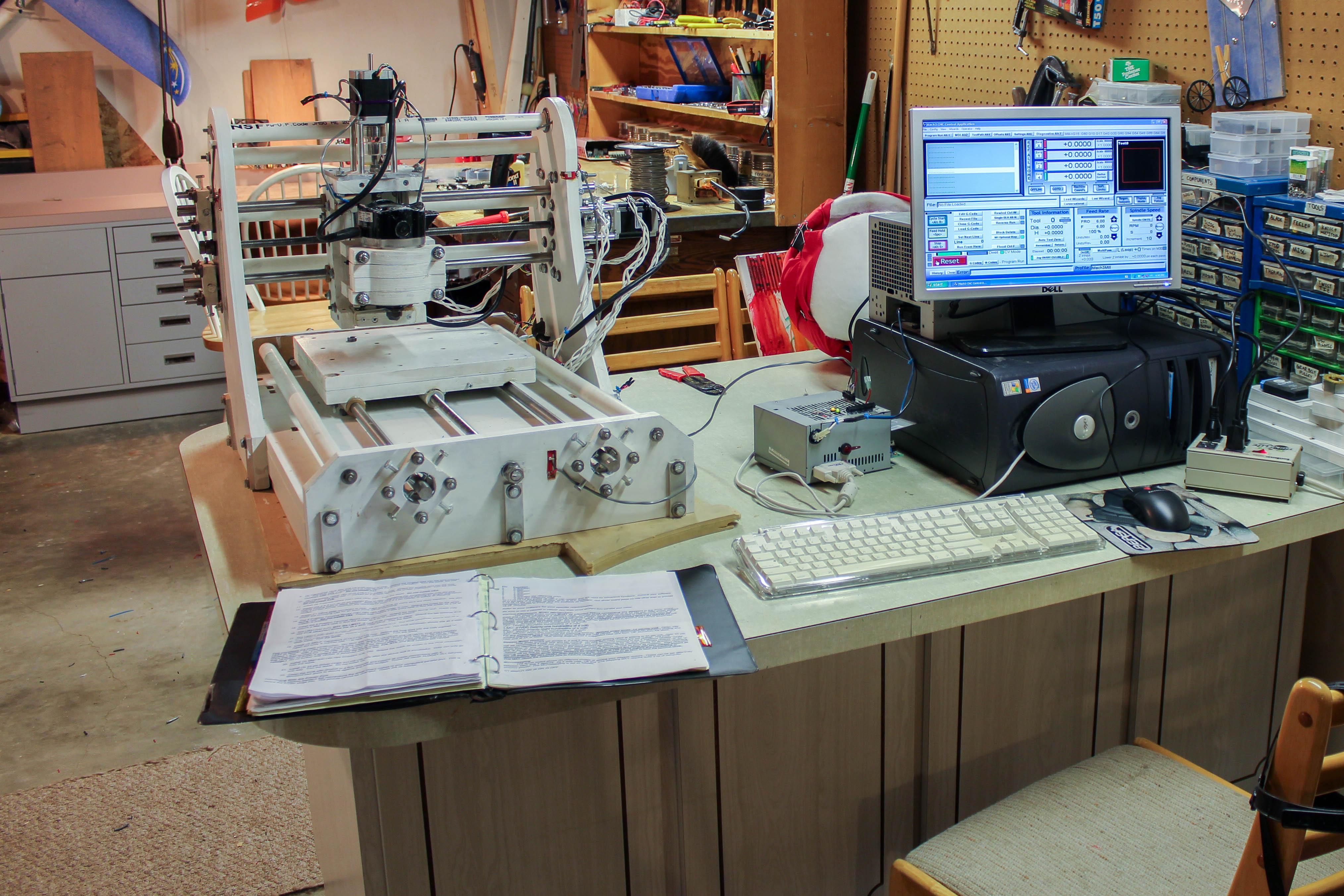
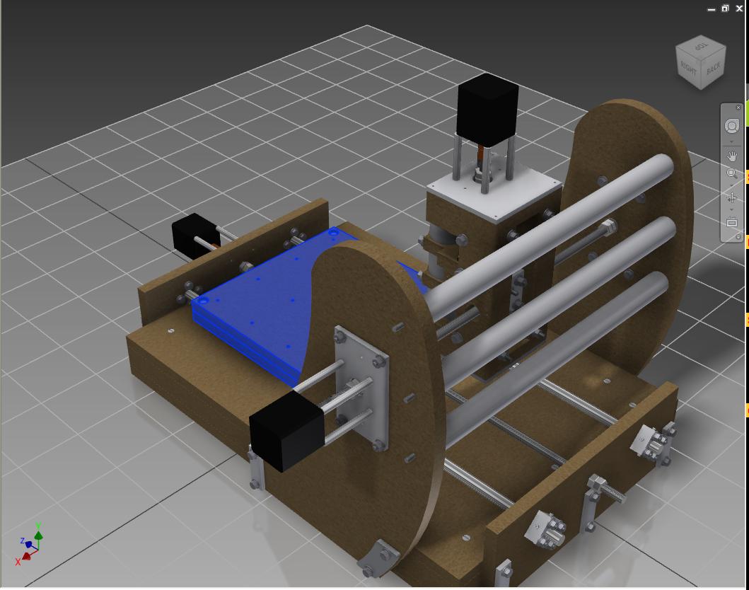
Designing and Building a CNC Machine
I designed and built a CNC machine with 12″x12″x4″ of cutting space. It uses 270 oz-in steppers, a regular old router, a HobbyCNC controller, and Mach 3 as the driving software. It’s accurate down to at least 1/100″. It cost $400 and is made mostly from MDF. Because it is made of wood, it is designed to be very accurate and adjustable.
Originally I designed it for PCB Isolation Routing. Now, ordering prototype PCB boards online is so cheap, that it isn’t worth my time to route myself. It is great for carving wood, making signs, engraving, and other odd jobs. Read more about the design here. I sold it in 2017.