I usually forget bitwise operators, basic variables, and functions when coding in Atmel Studio for an ATtiny or ATmega project.
Normally, I look at some of my old code for reference. This is my focused and consolidated version of the important building blocks.
Contents
I/O Registers
- DDRx - Data Direction Register - Configures each pin as an input or output. The 0th bit refers to the 0th pin of the port and the 7th bit refers to the 7th bit of the port.
- PORTx - Data Register - The value of the pin, used for reading input or writing output
- Pxn - The nth bit of port x. PB0 refers to the 0th bit of port B and PE7 refers to the 7th bit of port E.
- x - letter (e.g. B, D, E, F, G)
- n - number (0, 1, 2, … 7)
Note that you still should refer to the datasheet for the specifics on these registers and how to set their values.
Bitwise Operators
These commands affect a specific bit in the register without changing other values in the register.
// ON - writes a 1. Makes Port B, Pin 3 output high
PORTB |= ( 1 << PB3);

// OFF - writes a 0. Makes Port B, Pin 3 output low
PORTB &= ~( 1 << PB3 );

// TOGGLE - toggles the current value - a 0 will change to a 1 and a 1 will change to a 0
PORTB ^= ( 1 << PB3 );
Writing multiple bits in one line. Many people are cautious about this. Be brave.
// ON - writes a 1 to multiple bits
PORTB |= ( 1 << PB3 ) | ( 1 << PB5 ) | ( 1 << PB6 );

// OFF - writes a 0 to multiple bits
PORTB &= ~( 1 << PB3) & ~( 1 << PB5 ) & (1 << PB6);  // Writes 0 to multiple bits

// TOGGLE - toggles the current value of multiple bits
PORTB ^= ( 1 << PB3) ^ (1 << PB5 ) ^ ( 1 << PB6 );
Delays
#define F_CPU 8000000UL // speed of clock, before prescaler (default 8MHz)
#include <util/delay.h>

int main(void) {

  _delay_ms(100);  // wait 100 milliseconds

  _delay_us(100); // wait 100 microseconds

}
Blinking LED Example
#define F_CPU 8000000UL // speed of clock, before prescaler (default 8MHz)

#include <avr/io.h>
#include <util/delay.h>

int main(void) {

  DDRB |= ( 1 << PB3);  // this command makes the 3rd bit of port B an output

  while (1) {

    PORTB |= ( 1 << PB3); // make Port B, Pin 3 output high

    _delay_ms(1000);  // wait 1 second

    PORTB &= ~( 1 << PB3 ); // make Port B, Pin 3 output low

    _delay_ms(1000);  // wait 1 second

  }

}
Interrupts
This example is the minimum code for an interrupt. Refer to the datasheet for a list of all interrupts.
#include <avr/interrupt.h>;

///////////////////////////////////////////////////////////////////////////////////////
// @name: Timer 0 Compare A Interrupt
// @call: When OCR0A is equal to compare value
///////////////////////////////////////////////////////////////////////////////////////
ISR(TIM0_COMPA_vect){

// interrupt code here

}

int main(void) {

// set registers for Timer 0

// enable Output Compare Interrupts in Timer 0 registers

sei();  // enable interrupts

while(1);  // wait for interrupts

}
Program Memory
This is for storing and reading large data to program memory.
#include <avr/pgmspace.h>;

// writing to program memory

const unsigned char ANTI_LOG[] PROGMEM = {
  0x00, 0x00, 0x00, 0x00, 0x00, 0x00, 0x00, 0x00, 0x00, 0x00, 0x01, 0x01, 0x01, 0x01, 0x01, 0x01,
  0x01, 0x01, 0x01, 0x01, 0x01, 0x01, 0x01, 0x01, 0x01, 0x02, 0x02, 0x02, 0x02, 0x02, 0x02, 0x02,
  0x02, 0x02, 0x03, 0x03, 0x03, 0x03, 0x03, 0x03, 0x04, 0x04, 0x04, 0x04, 0x04, 0x05, 0x05, 0x05,
  0x05, 0x06, 0x06, 0x06, 0x07, 0x07, 0x07, 0x08, 0x08, 0x08, 0x09, 0x09, 0x0A, 0x0A, 0x0B, 0x0B,
  0x0C, 0x0C, 0x0D, 0x0D, 0x0E, 0x0F, 0x0F, 0x10, 0x11, 0x11, 0x12, 0x13, 0x14, 0x15, 0x16, 0x17,
  0x18, 0x19, 0x1A, 0x1B, 0x1C, 0x1D, 0x1F, 0x20, 0x21, 0x23, 0x24, 0x26, 0x27, 0x29, 0x2B, 0x2C,
  0x2E, 0x30, 0x32, 0x34, 0x36, 0x38, 0x3A, 0x3C, 0x3E, 0x40, 0x43, 0x45, 0x47, 0x4A, 0x4C, 0x4F,
  0x51, 0x54, 0x57, 0x59, 0x5C, 0x5F, 0x62, 0x64, 0x67, 0x6A, 0x6D, 0x70, 0x73, 0x76, 0x79, 0x7C,
  0x7F, 0x82, 0x85, 0x88, 0x8B, 0x8E, 0x91, 0x94, 0x97, 0x9A, 0x9C, 0x9F, 0xA2, 0xA5, 0xA7, 0xAA,
  0xAD, 0xAF, 0xB2, 0xB4, 0xB7, 0xB9, 0xBB, 0xBE, 0xC0, 0xC2, 0xC4, 0xC6, 0xC8, 0xCA, 0xCC, 0xCE,
  0xD0, 0xD2, 0xD3, 0xD5, 0xD7, 0xD8, 0xDA, 0xDB, 0xDD, 0xDE, 0xDF, 0xE1, 0xE2, 0xE3, 0xE4, 0xE5,
  0xE6, 0xE7, 0xE8, 0xE9, 0xEA, 0xEB, 0xEC, 0xED, 0xED, 0xEE, 0xEF, 0xEF, 0xF0, 0xF1, 0xF1, 0xF2,
  0xF2, 0xF3, 0xF3, 0xF4, 0xF4, 0xF5, 0xF5, 0xF6, 0xF6, 0xF6, 0xF7, 0xF7, 0xF7, 0xF8, 0xF8, 0xF8,
  0xF9, 0xF9, 0xF9, 0xF9, 0xFA, 0xFA, 0xFA, 0xFA, 0xFA, 0xFB, 0xFB, 0xFB, 0xFB, 0xFB, 0xFB, 0xFC,
  0xFC, 0xFC, 0xFC, 0xFC, 0xFC, 0xFC, 0xFC, 0xFC, 0xFD, 0xFD, 0xFD, 0xFD, 0xFD, 0xFD, 0xFD, 0xFD,
  0xFD, 0xFD, 0xFD, 0xFD, 0xFD, 0xFD, 0xFD, 0xFE, 0xFE, 0xFE, 0xFE, 0xFE, 0xFE, 0xFE, 0xFF, 0xFF};

int main(void) {
  // reading from program memory
  OCR0A = pgm_read_byte(&ANTI_LOG[3]); // write the value at index 3 of ANTI_LOG to register OCR0A

}
PWM
Simple PWM is accomplished by setting a timer and using the hardware based Output Compare and PWM.
The following examples were written on an ATtiny 45, but should work for an ATtiny25, ATtiny45, and ATtiny85. Other Atmel microcontrollers can be used with slight, if any, modification.
/*
 * Simple PWM
 * Produces a PWM output on OC0A (PB0)
 */

#include <avr/io.h>

int main(void) {

  // configure Timer 0
  TCCR0A |= (1 << COM0A1) | (1 << COM0A0) | (1 << WGM01) | (1 << WGM00); // Fast PWM on OC0A
  OCR0A = 0x50; // OCR0A controls the duty cycle
  TCCR0B |= (1 << CS01); // Clock = prescaler/8

}
This code does the exact same thing as the code above, but uses interrupts. This will set us up for solving complex situations in the future.
/*
 * Simple PWM using Interrupts
 * Produces a PWM output on OC0A (PB0)
 */

#include <avr/io.h>
#include <avr/interrupt.h>

///////////////////////////////////////////////////////////////////////////////////////
// @name: Timer 0 Overflow Interrupt
// @call: When Timer 0 overflows
// @note: Used for 10-bit fast PWM output
///////////////////////////////////////////////////////////////////////////////////////
ISR(TIM0_OVF_vect) {

  PORTB |= ( 1 << PB0 );  // turn on output

}

///////////////////////////////////////////////////////////////////////////////////////
// @name: Timer 0 Compare A Interrupt
// @call: When OCR0A is equal to compare value
// @note: Used for 10-bit fast PWM output
///////////////////////////////////////////////////////////////////////////////////////
ISR(TIM0_COMPA_vect){

  PORTB &= ~( 1 << PB0);  // turn off output

}

int main(void) {

  // set registers for Timer 0
  TCCR0A |= (1 << WGM01) | (1 << WGM00); // Fast PWM, OC0A disconnected
  OCR0A = 0x50; // Initial duty cycle
  TCCR0B |= (1 << CS01); // Clock = prescaler/8

  DDRB |= ( 1 << PB0 );  // enable output

  sei();  // enable interrupts

  while(1);

}
This example addresses how to change the PWM duty cycle. Note this example does not use any delay functions.
/*
 * PWM using Interrupts
 * Produces a PWM that glows on an off gradually on OC0A (PB0)
 */

#define F_CPU 8000000UL  // speed of clock, before prescaler (default 8MHz)

#include <avr/io.h>
#include <avr/interrupt.h>

unsigned char cyclesPWM = 0; // counts number of PWM cycles
unsigned char dutyPWM = 20; // 0 = 0% duty cycle, 255 = 100% duty cycle
char indexDirPWM = 1; // 1 = increase duty cycle, -1 = decrease duty cycle

///////////////////////////////////////////////////////////////////////////////////////
// @name: Timer 0 Overflow Interrupt
// @call: When Timer 0 overflows
// @note: Used for 10-bit fast PWM output
///////////////////////////////////////////////////////////////////////////////////////
ISR(TIM0_OVF_vect) {

  cyclesPWM++;
  if (cyclesPWM >= 10){ // change the duty cycle every 10th cycle
    cyclesPWM = 0; // e.g. change PWM every 10th overflow

    cyclesPWM += indexDirPWM; // adjust PWM duty cycle by 1

    if (dutyPWM >= 254) // if duty cycle = 100%,
    indexDirPWM = -1; // ramp down
    else if (dutyPWM <= 0) // else if duty cycle = 0%
    indexDirPWM = 1; // ramp up

    OCR0A = dutyPWM;
  }

  PORTB |= ( 1 << PB0 ); // turn on output

}

///////////////////////////////////////////////////////////////////////////////////////
// @name: Timer 0 Compare A Interrupt
// @call: When OCR0A is equal to compare value
// @note: Used for 10-bit fast PWM output
///////////////////////////////////////////////////////////////////////////////////////
ISR(TIM0_COMPA_vect){

  PORTB &= ~( 1 << PB0); // turn off output

}

int main(void) {

  TCCR0A |= (1 << WGM01) | (1 << WGM00); // Fast PWM, OC0A disconnected
  OCR0A = 0x50; // Initial duty cycle
  TCCR0B |= (1 << CS01); // Clock = prescaler/8

  sei();  // enable interrupts

  while(1);

}
The simple linear PWM ramp in the example above doesn’t look good when driving an LED seen by the human eye.
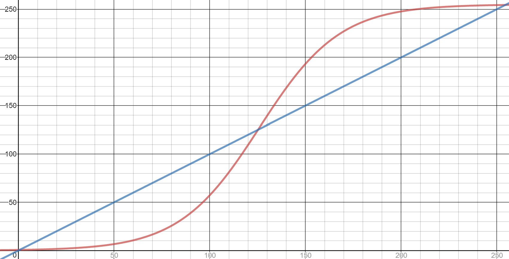 simple linear ramp and anti-log ramp
This example addresses that issue with a non-linear change in the duty cycle. An anti log function works best. The values came from user BG100 on Stack Overflow.
/*
* Non-Linear PWM using Interrupts
* Produces a non-linear PWM that glows on an off gradually on OC0A (PB0)
*/
#include <avr/io.h>
#include <avr/interrupt.h>
#include <avr/pgmspace.h>
#define F_CPU 8000000UL // speed of clock, before prescaler (default 8MHz)
const unsigned char ANTI_LOG[] PROGMEM = {
0x00, 0x00, 0x00, 0x00, 0x00, 0x00, 0x00, 0x00, 0x00, 0x00, 0x01, 0x01, 0x01, 0x01, 0x01, 0x01,
0x01, 0x01, 0x01, 0x01, 0x01, 0x01, 0x01, 0x01, 0x01, 0x02, 0x02, 0x02, 0x02, 0x02, 0x02, 0x02,
0x02, 0x02, 0x03, 0x03, 0x03, 0x03, 0x03, 0x03, 0x04, 0x04, 0x04, 0x04, 0x04, 0x05, 0x05, 0x05,
0x05, 0x06, 0x06, 0x06, 0x07, 0x07, 0x07, 0x08, 0x08, 0x08, 0x09, 0x09, 0x0A, 0x0A, 0x0B, 0x0B,
0x0C, 0x0C, 0x0D, 0x0D, 0x0E, 0x0F, 0x0F, 0x10, 0x11, 0x11, 0x12, 0x13, 0x14, 0x15, 0x16, 0x17,
0x18, 0x19, 0x1A, 0x1B, 0x1C, 0x1D, 0x1F, 0x20, 0x21, 0x23, 0x24, 0x26, 0x27, 0x29, 0x2B, 0x2C,
0x2E, 0x30, 0x32, 0x34, 0x36, 0x38, 0x3A, 0x3C, 0x3E, 0x40, 0x43, 0x45, 0x47, 0x4A, 0x4C, 0x4F,
0x51, 0x54, 0x57, 0x59, 0x5C, 0x5F, 0x62, 0x64, 0x67, 0x6A, 0x6D, 0x70, 0x73, 0x76, 0x79, 0x7C,
0x7F, 0x82, 0x85, 0x88, 0x8B, 0x8E, 0x91, 0x94, 0x97, 0x9A, 0x9C, 0x9F, 0xA2, 0xA5, 0xA7, 0xAA,
0xAD, 0xAF, 0xB2, 0xB4, 0xB7, 0xB9, 0xBB, 0xBE, 0xC0, 0xC2, 0xC4, 0xC6, 0xC8, 0xCA, 0xCC, 0xCE,
0xD0, 0xD2, 0xD3, 0xD5, 0xD7, 0xD8, 0xDA, 0xDB, 0xDD, 0xDE, 0xDF, 0xE1, 0xE2, 0xE3, 0xE4, 0xE5,
0xE6, 0xE7, 0xE8, 0xE9, 0xEA, 0xEB, 0xEC, 0xED, 0xED, 0xEE, 0xEF, 0xEF, 0xF0, 0xF1, 0xF1, 0xF2,
0xF2, 0xF3, 0xF3, 0xF4, 0xF4, 0xF5, 0xF5, 0xF6, 0xF6, 0xF6, 0xF7, 0xF7, 0xF7, 0xF8, 0xF8, 0xF8,
0xF9, 0xF9, 0xF9, 0xF9, 0xFA, 0xFA, 0xFA, 0xFA, 0xFA, 0xFB, 0xFB, 0xFB, 0xFB, 0xFB, 0xFB, 0xFC,
0xFC, 0xFC, 0xFC, 0xFC, 0xFC, 0xFC, 0xFC, 0xFC, 0xFD, 0xFD, 0xFD, 0xFD, 0xFD, 0xFD, 0xFD, 0xFD,
0xFD, 0xFD, 0xFD, 0xFD, 0xFD, 0xFD, 0xFD, 0xFE, 0xFE, 0xFE, 0xFE, 0xFE, 0xFE, 0xFE, 0xFF, 0xFF};
unsigned char cyclesPWM = 0;
char indexDirPWM = 1;
unsigned char indexPWM = 70;
///////////////////////////////////////////////////////////////////////////////////////
// @name: Timer 0 Overflow Interrupt
// @call: When Timer 0 overflows
// @note: Used for 10-bit fast PWM output
///////////////////////////////////////////////////////////////////////////////////////
ISR(TIM0_OVF_vect) {
cyclesPWM++;
if (cyclesPWM >= 10){ // change the duty cycle every 10th cycle
cyclesPWM = 0; // e.g. change PWM every 10th overflow
indexPWM += indexDirPWM; // adjust PWM index
if (indexPWM >= 254) // if duty cycle = 100%,
indexDirPWM = -1; // ramp down
else if (indexPWM <= 0) // else if duty cycle = 0%
indexDirPWM = 1; // ramp up
OCR0A = pgm_read_byte(&ANTI_LOG[indexPWM]); // set new PWM
}
PORTB |= ( 1 << PB0 ); // turn on output
}
///////////////////////////////////////////////////////////////////////////////////////
// @name: Timer 0 Compare A Interrupt
// @call: When OCR1A is equal to compare value
// @note: Used for 10-bit fast PWM output
///////////////////////////////////////////////////////////////////////////////////////
ISR(TIM0_COMPA_vect){
PORTB &= ~( 1 << PB0 ); // turn off output
}
int main(void) {
TCCR0A |= (1 << WGM01) | (1 << WGM00); // Fast PWM, OC0A disconnected
OCR0A = 0x50; // Initial duty cycle
TCCR0B |= (1 << CS01); // Clock = prescaler/8
sei(); // enable interrupts
while(1);
}
If there is any reference info you find useful that isn’t included, comment below!