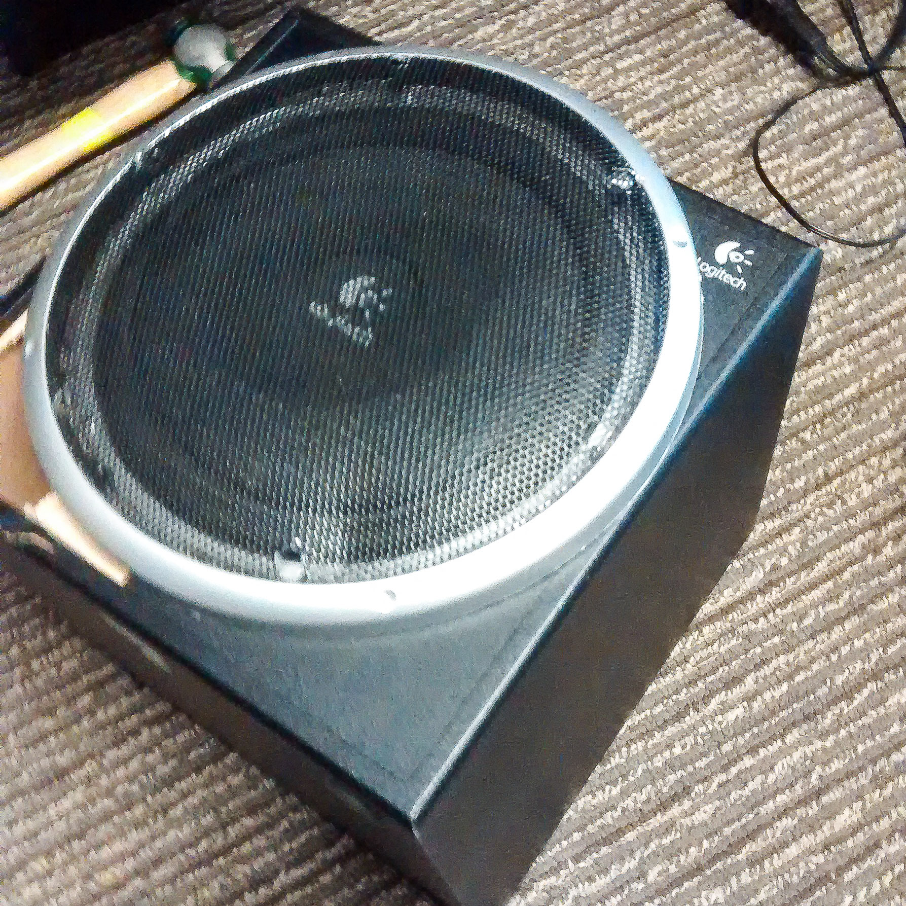
Logitech has a large presence in 2.1 systems, where price and appearance dominate. This sub is designed to trick you, there’s more to it than what meets the eye.
I picked up a used Logitech Z340 2.1, sans the 2. I got a woofer with no satellites or volume control.
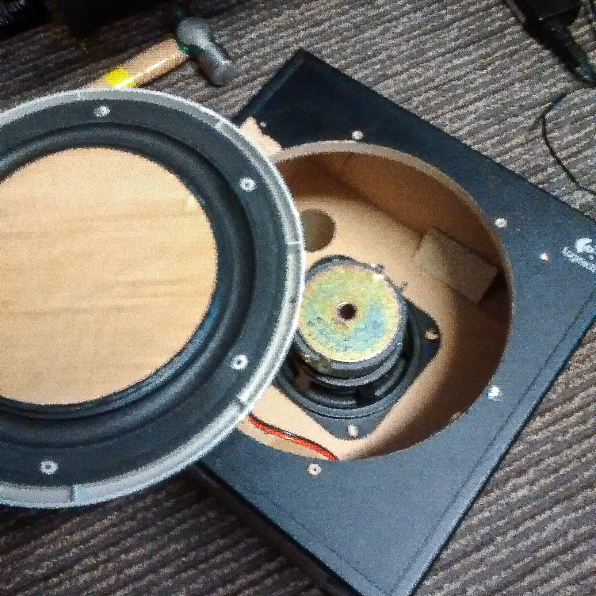
Since I don’t have the satellites, this is of no value to me. And the speaker isn’t of much value either, so I want the amplifier out of this.

This sub requires a lot of hammering and unscrewing to free the amp. If you had long needlenose pliers, you could get to the amp without destroying the box. Otherwise, you will have to rip off the front Revolutionary Subwoofer Panel and smash open the screw-free, super glued box.
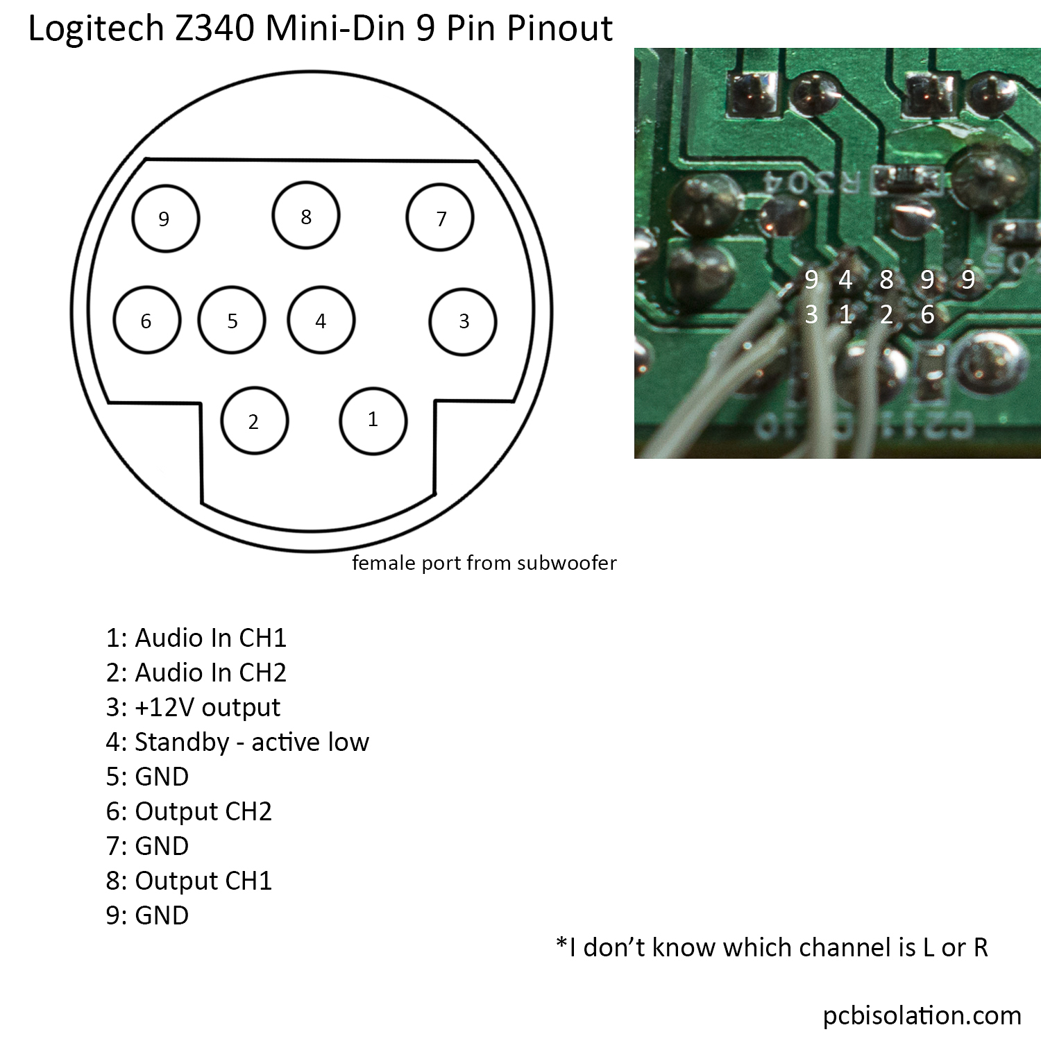
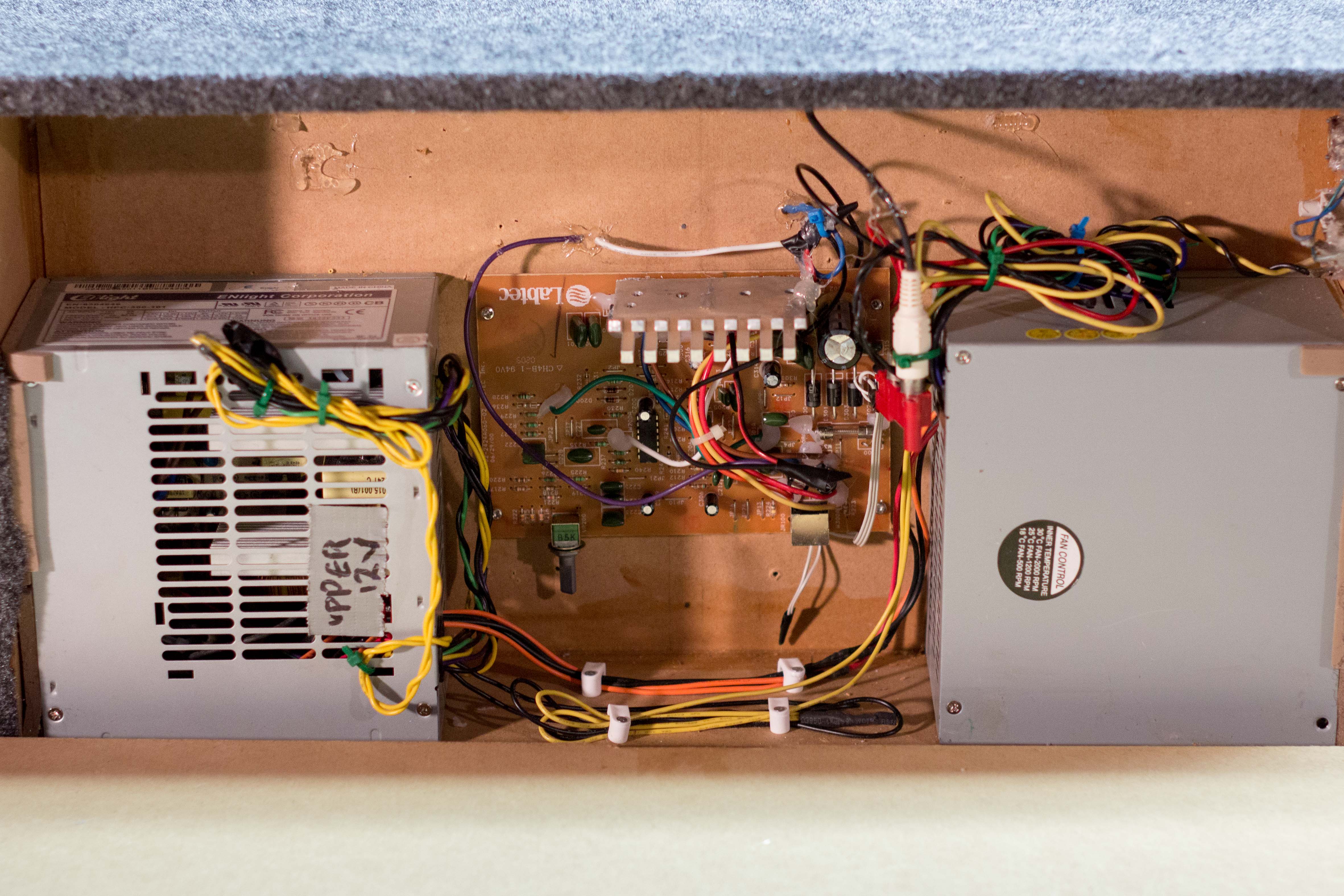
Fortunately, everything here is simple. The picture of the PCB is where the mini-din connector attaches to the PCB.
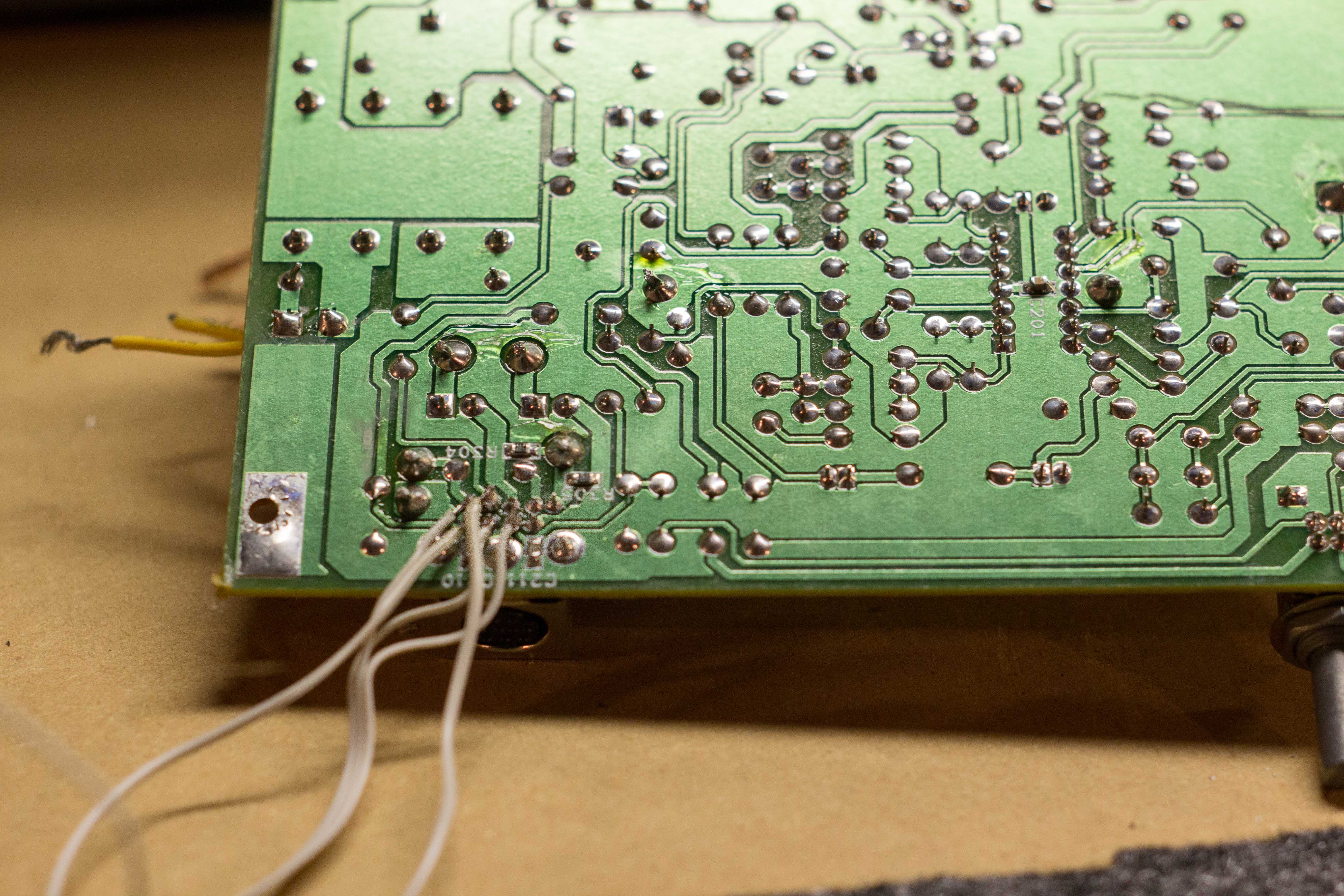
You can see where I attached wires to control the subwoofer. I shorted the standby signal to the 12V out, so it is always on.
The amp will be replacing the Sure amp that broke from my Kicker Sub Build.
Here it is, powered from the 12V rail of an ATX PSU. Since the Sure amp is gone, the 2nd PSU isn’t used anymore.
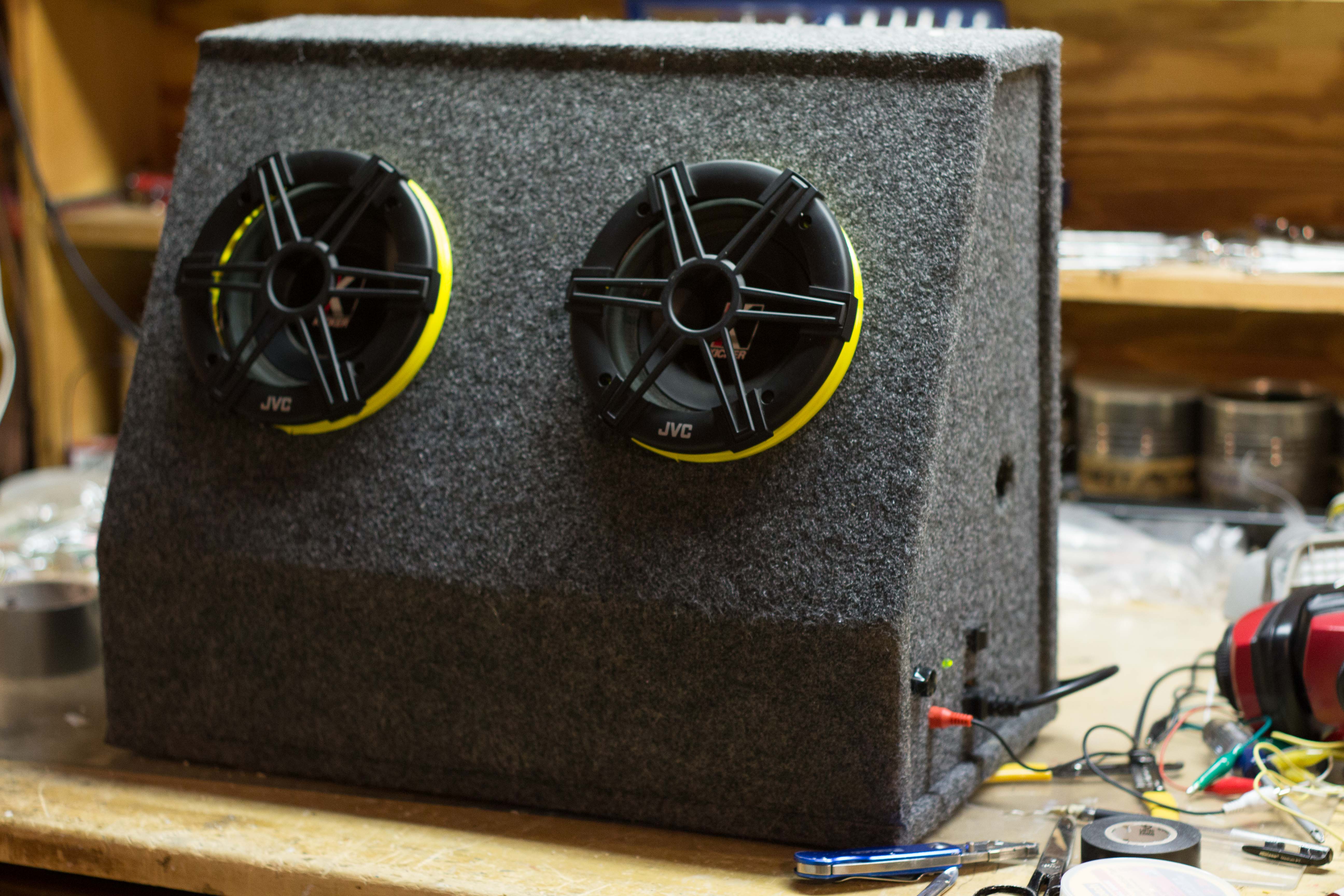
And there you have it, a Logitech Z340 that would have surely gone to the dump, repurposed and reused.
Hi
i recently purchase the same subwoofer, but without the min din cable. the picture shows the 12v psu powering the amp, does the logitech amp takes 12v power input?
The Z340 takes mains AC in and steps it down to 14.4V, I believe. The chip is a TDA7375, which is actually a car amp. 12V-14.4V is a good range, although the datasheet says it will accept 8V-18V.
And yes, I removed the transformer, skipped the rectification and smoothing stage, and fed the amp 12V from a psu. You can find where to feed 12V, by tracing to the end of the rectification stage, by the large capacitor.
how would i connect music to this amp
Hi there, and thanks for sharing your project!
I have the subwoofer unit but without the other two small speakers. I’ve used the directions in this post to connect the output of the subwoofer to two speakers and the input of the subwoofer to my desktop PC.
Now, my question is: How do I control the volume of the two speakers using a potentiometer ?
Thanks!
Hi David,
The potentiometer will go in between the audio source and ground, like this.
Since you have a left and right channel, you’ll need a dual-gang pot. This lets one knob control two channels. You’ll wire it like this.
Hi
I’m trying to make a car sub from this. I followed your instructions and connected the sub out of my car head unit directly to pins 1, 2 and 5(mass). The sub does turn on but all I can get is a very very quiet sound from it (I turned to the max the sub volume on my head unit).
What do you think is wrong?
Also where exactly did you solder the +12 and -12V?
Tnx.
I’d confirm the audio source is good. Try playing music directly from your phone to the amp.
I soldered the +12V and GND on the underside of the PCB, on the leads of the filtering cap – the enormous one in upper right of the board. The cap has polarity markings. The GND goes to the negative lead of the cap and +12V to the positive lead. https://en.wikipedia.org/wiki/Electrolytic_capacitor#/media/File:Polarity-wet-Al-Elcaps.jpg
Additionally, check your power line and make sure you are indeed getting +12V. Could be a bad ground, too.
Thanks.
I’ve already had everything in a way you suggested. I can get a very quiet sound out of it, like 2 on a scale of 10. I remember it being very loud while it was serving as a comp speaker…
In the end it is actually working. Well, it is much quieter than I expected it to be, but if I pump up everything on my head unit to the max it becomes at least usable – well, you can’t expect miracles from a 4W speaker 🙂
Tnx for this tip.
The Internet is awesome! I’m in the process of almost exactly the same project (z-340 sub hack)! I need to look no further! Thanks a million for all of your efforts.
Glad to have helped! Good luck, too!
Hi there. Thanks for making this guide. I’ve unscrewed the panel where the amp is but the cables are so short. So I can’t pull it out. And I’m reluctant to smash up the box. Shall I get a cutter in there, cut the mains and the speaker wire. Then pull amp out. Solder extension leads. ?
Also am I right in saying I solder two leads to the biggest cap in there?
I am want to leave the circuit componants alone so I can take out of my car and plug AC in as normal. Obviously making sure my new 12v leads are insulated.
Sorry for the late response, David.
Yeah, I’d recommend you cut the wires to remove it.
And correct again, soldering power leads underneath the main cap is ok.
I want to use this amp (Z-340) to power a stand-alone Sony sub. I don’t need the speakers just the sub. I want to run it from my Onkyo receiver’s pre-amp sub output. I can see your wiring but the picture shows a jumble of wires coming from the circuit board that I cannot make out. Which leads do I need to solder to the circuit board to come in from the receiver pre-amp out? The pinout diagram does not show any input to the sub just audio ch1 and audio ch2. I am not an expert and need your help. Thanks so much for sharing your information. It’s a big help!
Gary,
Here’s my recommendation, assuming your sub out is a single RCA. Solder the outer ground wire of the RCA cable to GND of the Z-340 amp. Solder the inner wire to both the Audio In CH1 and CH2. The reasoning is below:
Normally, this amp takes a line level stereo channel and does three things with it. First, it amplifies the left side and sends it to the left speaker. Second, it amplifies the right side and sends it to the right speaker. Third, it sums the two signals, sends them through a low pass filter, amplifies that signal and sends it to the subwoofer.
The sub output of your amp has already applied the sum and low pass filter. No problem. We still feed that signal in to the same Audio In CH1 and CH2 inputs of this amp.
Love this project! Got a couple goodwill purchases this will support. A JVC bookshelf stereo FS-7000 for 14.99 (with the nice hardwood speakers) sounds great, but no bass from tiny speakers. So I picked up a Z-340 sub only for $6.99 and PCBISOLATION provided me with the pinouts I needed. I hope to use a panel mount RCA jack on the amp plate (if there’s room) feeding the signal from the FS-7000 subwoofer output. Hopefully the subwoofer feed is a low level output…
Do you know if I can/should combine the R/L inputs at my RCA input as to get both channels input to the Amp?
Any thoughts on my approach
Suggestions?
Thanks again, great site!
Matt
Or maybe two RCA panel jacks (plenty of room) fed by a “Y” cable from the single subwoofer output. That sounds safer.
Sorry, I should have read your previous reply. NVM and thanks for a great site!
Hi friend, I need help in the project, so I have to join the wires ch1 ch2 in + gnd, join ch1 ch2 out + gnd, and power the amplifier with 12v after the bridge rectifier? I’m going to use the box in the car, how do I turn it off when I turn off the radio?
Paulo,
Yes, those connections look correct.
Having the sub turn on and off with the radio may be more tricky. A relay controlled by some Power_OK or +12V out from the radio may work.
A simpler solution would be to manually control the sub with a power button.
Can I connect 12v of the car battery straight into the power input of the card ?? where was the transformer connected ??
Paulo,
If I remember correctly, the big capacitor on the amplifier is connected directly to the 12V rail. You can connect you 12V power to the terminals of this capacitor.
I’d measure and confirm the voltage underneath that capacitor before hooking up 12V.
Eu liguei tudo aqui e não funcionou será q tenho que juntar o stand by low a saída 12v ?
Standby should be connected to 12V to turn on the amp.
I have the z340 with the satellites, however as of last week they longer turn on when operating the switch on one of the pods, normally a led would light up and everything would be fine. checked the wiring and and the plug fuse and everything is in good order. It may just be the internal fuse on the amp but if not is there anyway to use the satellites say with a tv, or do they need to be powered.
Abbey,
The satellites are simply just speakers. Without the amplifier, they would not work with a TV.
Thank you Callahan for you reply
I have now opened the the sub and managed to get the amp out, the wiring inside the sub for anyone else thinking about it, is a little on the short side, so you may want to extend this before putting the amp back in.
Tested the output voltages on the pins and these fine, however the plugged in satellites will still not switch on, does anyone here have any ideas of what could be wrong and how to fix it.
Abbey,
If the amp is outputting the correct voltages, then perhaps the fault is in the satellites or it’s cables.
I need help to my logitech z540 subwooper no satilate speaker how to connect 9mini din pin out diagaram
Gary,
The diagram is in the post above. What are you asking for?
como puedo identificar los colores y coneccion de un equipo de bosinas para pc marca logitech s200 black
cable que va conectado a siael boffer se estrofio los pines y necesito conectarlos conforme van para no causar un daño
can you please tell me, what does it say on subwoofer speaker, what is the wattage of the speaker?
I just bought the same unit from a thrift store for a project. Thanks for the guide, very helpful!
can somebody help me?
Where find Z340 mini din (mother)
Thank you for helping me Best regard
This was a great starting point, but I found my Pinout was different from that listed here. I wanted to just use the subwoofer with a pair of bookshelf speakers I recently bought, to replace the two tiny satellite speakers. So I just wanted to put 2-channel stereo in to the subwoofer and have it supply bass. My pinout ended up being:
pin 1 – Orange: (from white shielded 2-wire); connect to Audio in Left.
pin 2 – Brown: (from white sheilded 2-wire); connect to Audio in Right
pin 3 – Purple: Right Speaker +; unused.
pin 4 – Green: Ground; unused
pin 5 – Yellow: Enable; Connect to RED +12v
pin 6 – Red: +12v; Connect to Yellow Enable
pin 7 – Grey: Left Speaker -; unused
pin 8 – Blue: Left Speaker +; unused
pin 9 – Black: Right Speaker -; unused
And connect the audio in shield (ground) to the shield on the white pair (gnd).
That worked for me.
Hope that is useful. I followed the same mini-DIN-9 connector numbering diagram given elsewhere in this post.
I got the Speaker Left/Right +/- wiring info from taking apart the satellite speaker with all the controls, those were labels on that PCB. Unfortunately the rest of the signals were not marked, I just did some detective work with an ohmmeter and voltmeter to deduce the other signals.
My speaker looked exactly like the one in the pictures from this post, not sure why the pinout differed. My speaker had M/N = S-LBH51.
Thanks for the informative post!
I have the S-LBH51 too. I don’t think it’s quite the same as the box discussed in this post. There’s a plate with many screws on the back that the amp is mounted to and the board is oriented vertically, but best I can guess from the photos here that box had 1) no plate, 2) the amp on the bottom oriented horizontally. I don’t know whether the amp board itself is different or not, I haven’t opened the box.
The “subwoofer” here isn’t entirely a trick– it actually manages to produce good clean output in a 5dB range from about 45Hz to 170Hz, at least at low levels. I’ve seen much larger HTIB “subwoofers” that are much worse. The satellite speakers are not nearly so good, though. They measure better than they sound, and they don’t measure very well.
The system is a little weirdly complicated: the right satellite has a 4560D op amp that either drives a headphone jack, or the main amps in the “subwoofer” box, whose output is then returned to the right satellite for distribution to the two satellite speakers. So in one sense, they’re just speakers, but the right one is not just a speaker…
Thanks for this post, I’m inspired to try 1) some better speakers as satellites and 2) using the “subwoofer” box in my car (a Subaru BRZ) which has terrible sound quality at the bass end. I need to see what low pass/high pass filtering might have been implemented though.
I can’t believe there’s so much going on over the years with this little sub.
My z340 hack might be an easy one. Can I just use it as a sub, and not have it power anything else? So somehow plug an RCA (subwoofer out from soundbar) into the z340?
I thought I could maybe use a 9-Pin to 3RCA AV Video Audio Cable Adapter Cord… I just didn’t want power coming back to the soundbar somehow hehehe!!
Thoughts from you knowledgeable folk appreciated 🙂
can someone tell me where to find circuit daigram of logitech z-340 please
Hola buenas me podrias ayudar con disgrama de como conectar la pura placa?
subwoofer
front panel Pin Wire
color Pin
Name Description
1 black R.SIG right computer signal (entering the subwoofer)
2 blue R.AMP1 amplified right signal (going from the subwoofer back to the satellites speaker)
3 red L.SIG left computer signal (entering the subwoofer)
4 yelow VCC +VCC (about 14,5V DC)
5 white V+ power ON – set to GND by 1k OHM resistor
6 orange R.AMP2 amplified right signal (going from the subwoofer back to the satellites speaker)
7 green L.GND ground for audio pin 3
8 violet R.GND ground for audio pin 1
9 brown HEADPHONES signal to the subwoofer that the headphones are connected (then it should go in silent mode). send GND to the pin 9 the subwofer and satelites MUTE
shield must be connected to GND
https://pinoutguide.com/Audio-Video-Hardware/creative_t3100_speakers_pinout.shtml
Is there anyway to connect the 9 pin to just RCA jacks to make it work for my tv surround
Great blog!! I just want to say, I’ve had this Z340 since about 2005, going based on my divorce. It had been stored away for years. I recently got hooked with audio again and was trying to some loud speakers for my 65″ Samsung TV and my computer. Well guess what? I pulled these speakers from a pile of speakers and cables that I had in a closet. Connected the 3.5mm to my computer and I just can’t believe the power and sound quality I had been missing for years. The boom on that Sub is amazing. The loudness on the speakers is much more than I can handle with out bothering my neighbors. So then I pulled a small BT board I bought on amazon to convert 3.5 to BT In and was able to connect it via BT to my TV. Amazing, just stunning! and I’ve spent few hundreds buying Pyle and other amps trying to use a bunch of huge speakers I had laying around. It all turns down to, I’m Loving these old speakers every day some more !
I’m glad you got them working again and connected via bluetooth!